LT5520 Ver la hoja de datos (PDF) - Linear Technology
Número de pieza
componentes Descripción
Fabricante
LT5520 Datasheet PDF : 12 Pages
| |||
LT5520
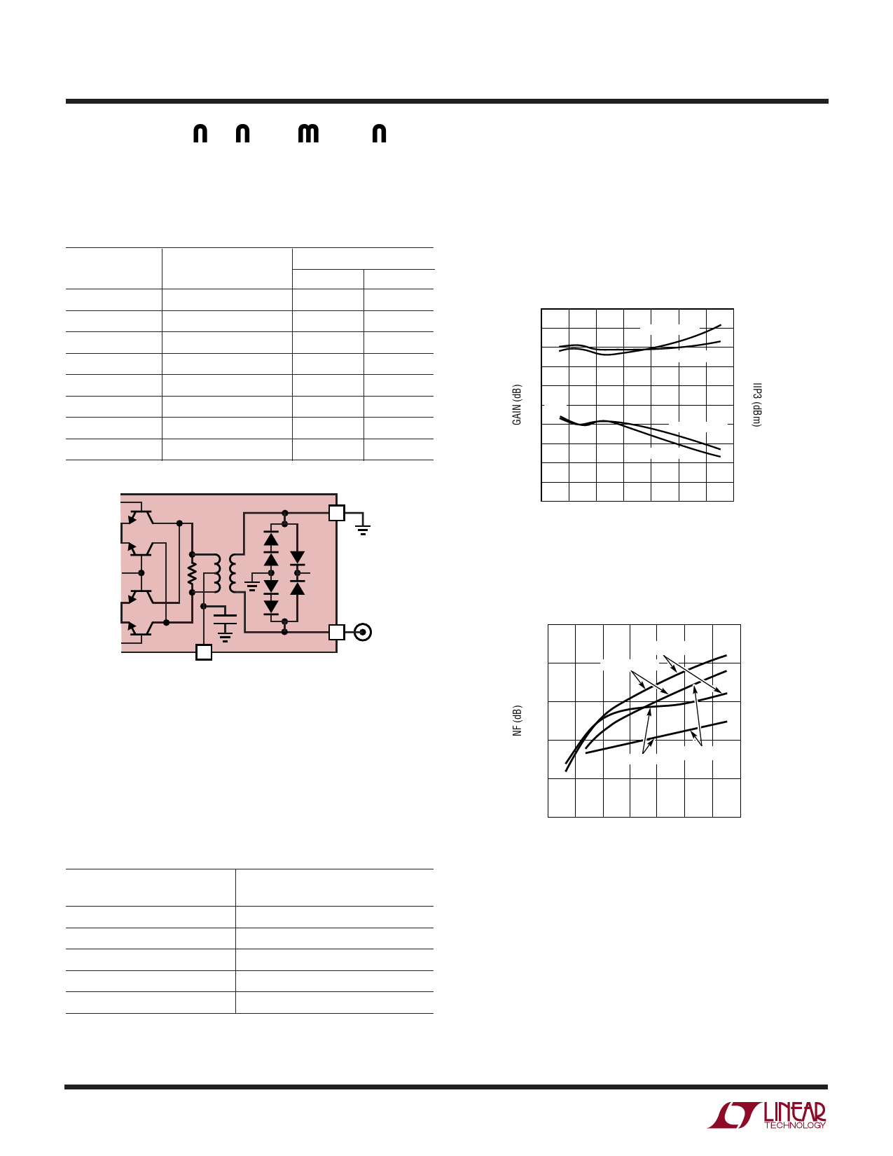
APPLICATIO S I FOR ATIO
The impedance data for the RF output, listed in Table 3, can
be used to develop matching networks for different load
impedances.
Table 3. Single-Ended RF Output Impedance
Frequency
(MHz)
Input
Impedance
S11
Mag
Angle
1300
26.9 + j38.2
0.520
94.7
1500
44.2 + j35.7
0.359
78.4
1700
53.9 + j20.6
0.198
68.0
1900
49.5 + j7.97
0.080
88.9
2100
42.8 + j4.14
0.089
148
2300
38.9 + j5.41
0.139
151
2500
38.7 + j7.78
0.154
140
2700
41.1 – j9.51
0.142
127
RF+ 11
VCC
The performance was evaluated with the input tuned for
each of these frequencies and the results are summarized
in Figures 6-8. The same IF input balun transformer was
used for all measurements. In each case, the LO input
frequency was adjusted to maintain an RF output fre-
quency of 1900 MHz.
5
20
4
IIP3
3
2
LOW SIDE LO
18
16
HIGH SIDE LO
14
1
12
0 GAIN
–1
–2
–3
10
LOW SIDE LO 8
6
HIGH SIDE LO
4
–4
2
–5
0
0
100 200 300 400 500 600 700
INPUT FREQUENCY (MHz)
5520 F06
Figure 6. Conversion Gain and IIP3
vs Tuned IF Input Frequency
RF– 10
8
LT5520
5520 F05
VCC
Figure 5. RF Output Circuit
RFOUT
50Ω
18
PLO = –5dBm
17
HIGH SIDE LO
16
Operation at Different Input Frequencies
On the evaluation board shown in Figure 10, the input of
the LT5520 can be easily matched for different frequencies
by changing the input capacitors, C1 and C2. Table 4 lists
some actual values used at selected frequencies.
Table 4. Input Capacitor Values vs Frequency
Frequency
(MHz)
Capacitance (C1, C2)
(pF)
70
820
140
220
240
68
480
18
650
12
15
LOW SIDE LO PLO = 0dBm
14
13
0
100 200 300 400 500 600 700
INPUT FREQUENCY (MHz)
5520 F07
Figure 7. SSB Noise Figure vs Tuned IF Input Frequency
5520f
8
Share Link: 