LT3580EDD-TRPBF Ver la hoja de datos (PDF) - Linear Technology
Número de pieza
componentes Descripción
Fabricante
LT3580EDD-TRPBF
Linear Technology

LT3580EDD-TRPBF Datasheet PDF : 28 Pages
| |||
LT3580
OPERATION
SEPIC Topology
The LT3580 can be configured as a SEPIC (single-ended
primary inductance converter). This topology allows for
the input to be higher, equal, or lower then the desired
output voltage. Output disconnect is inherently built into
the SEPIC topology, meaning no DC path exists between the
input and output. This is useful for applications requiring
the output to be disconnected from the input source when
the circuit is in shutdown.
Inverting Topology
The LT3580 can also work in a dual inductor inverting
topology. The part’s unique feedback pin allows for the
inverting topology to be built by simply changing the
connection of external components. This solution results
in very low output voltage ripple due to inductor L2 in
series with the output. Abrupt changes in output capacitor
current are eliminated because the output inductor deliv-
ers current to the output during both the off-time and the
on-time of the LT3580 switch.
Start-Up Operation
Several functions are provided to enable a very clean
start-up for the LT3580.
• First, the SHDN pin voltage is monitored by an internal
voltage reference to give a precise turn-on voltage level.
An external resistor (or resistor divider) can be connected
from the input power supply to the SHDN pin to provide
a user-programmable undervoltage lockout function.
VIN > VOUT
OR
VIN = VOUT
OR
VIN < VOUT
+
C1
SHUTDOWN
L1 •
C2
VIN
SW
LT3580
SHDN
FB
D1
•
L2
R1
RT
GND
+
VC
SYNC SS
RC
RT
CSS
CC
VOUT
C3
3580 F01
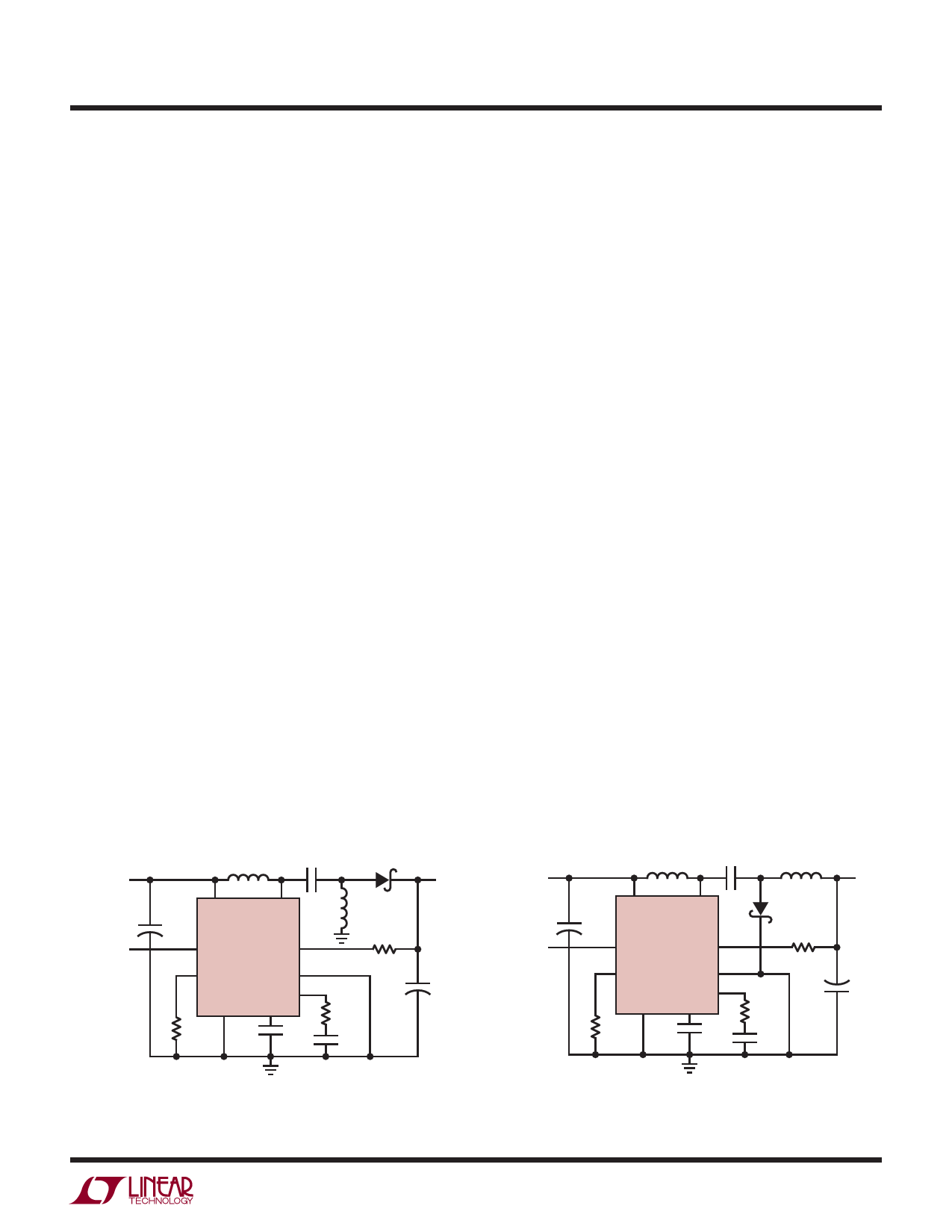
Figure 1. SEPIC Topology Allows for the Input to Span
the Output Voltage. Coupled or Uncoupled Inductors
Can Be Used. Follow Noted Phasing if Coupled
• Second, the soft-start circuitry provides for a gradual
ramp-up of the switch current. When the part is brought
out of shutdown, the external SS capacitor is first
discharged (providing protection against SHDN pin
glitches and slow ramping), then an integrated 275k
resistor pulls the SS pin up to ~2.2V. By connecting an
external capacitor to the SS pin, the voltage ramp rate
on the pin can be set. Typical values for the soft-start
capacitor range from 100nF to 1μF.
• Finally, the frequency foldback circuit reduces the
switching frequency when the FB pin is in a nominal range
of 350mV to 900mV. This feature reduces the minimum
duty cycle that the part can achieve thus allowing better
control of the switch current during start-up. When the
FB voltage is pulled outside of this range, the switching
frequency returns to normal.
Current Limit and Thermal Shutdown Operation
The LT3580 has a current limit circuit not shown in the
Block Diagram. The switch current is consistently moni-
tored and not allowed to exceed the maximum switch
current at a given duty cycle (see the Electrical Charac-
teristics table). If the switch current reaches this value,
the SR latch (SR1) is reset regardless of the state of the
comparator (A1/A2). Also not shown in the Block Diagram
is the thermal shutdown circuit. If the temperature of the
part exceeds approximately 165°C, the SR2 latch is set
regardless of the state of the comparator (A1/A2). A full
soft-start cycle will then be initiated. The current limit and
thermal shutdown circuits protect the power switch as well
as the external components connected to the LT3580.
VIN
+
C1
SHUTDOWN
L1 •
C2
VIN
SW
LT3580
SHDN
FB
• L2
D1
R1
VOUT
RT
GND
VC
SYNC SS
RC
RT
CSS
CC
C3
+
3580 F02
Figure 2. Dual Inductor Inverting Topology Results in
Low Output Ripple. Coupled or Uncoupled Inductors
Can Be Used. Follow Noted Phasing if Coupled
3580fg
7
Share Link: