LT3461A Ver la hoja de datos (PDF) - Linear Technology
Número de pieza
componentes Descripción
Fabricante
LT3461A Datasheet PDF : 8 Pages
| |||
LT3461/LT3461A
APPLICATIO S I FOR ATIO
Inductor Selection
The inductors used with the LT3461/LT3461A should
have a saturation current rating of 0.3A or greater. If the
device is used in an application where the input supply will
be hot-plugged, then the saturation current rating should
be equal to or greater than the peak inrush current. For the
LT3461, an inductor value between 10µH and 47µH,
depending upon output voltage, will usually be the best
choice for most designs. For the LT3461A, inductor values
between 4.7µH and 15µH inductor will suffice for most
applications. For best loop stability results, the inductor
value selected should provide a ripple current of 70mA or
more. For a given VIN and VOUT the inductor value to use
with LT3461A is estimated by the formula:
L (in microhenries) = D • VIN • VOUT •1sec
1A • 1V
where
D
=
VOUT + 1V – VIN
VOUT + 1V
Use twice this value for the LT3461.
Capacitor Selection
Low ESR capacitors should be used at the output to
minimize the output voltage ripple. Multilayer ceramic
capacitors using X5R/X7R dielectrics are preferred as they
have a low ESR and maintain capacitance over wide
voltage and temperature range. A 2.2µF output capacitor
is sufficient for most applications using the LT3461, while
a 1µF capacitor is sufficient for most applications using
the LT3461A. High output voltages typically require less
capacitance for loop stability. Always use a capacitor with
sufficient voltage rating.
Either ceramic or solid tantalum capacitors may be used
for the input decoupling capacitor, which should be placed
as close as possible to the LT3461/LT3461A. A 1µF
capacitor is sufficient for most applications.
Phase Lead Capacitor
A small value capacitor can be added across resistor R1
between the output and the FB pin to reduce output
perturbation due to a load step and to improve transient
response. This phase lead capacitor introduces a pole-
zero pair to the feedback that boosts phase margin near
the cross-over frequency. The following formula is useful
to estimate the capacitor value needed:
C PL
=
500kΩ
R2
• 1pF
For an application running 50µA in the feedback divider,
capacitor values from 10pF to 22pF work well.
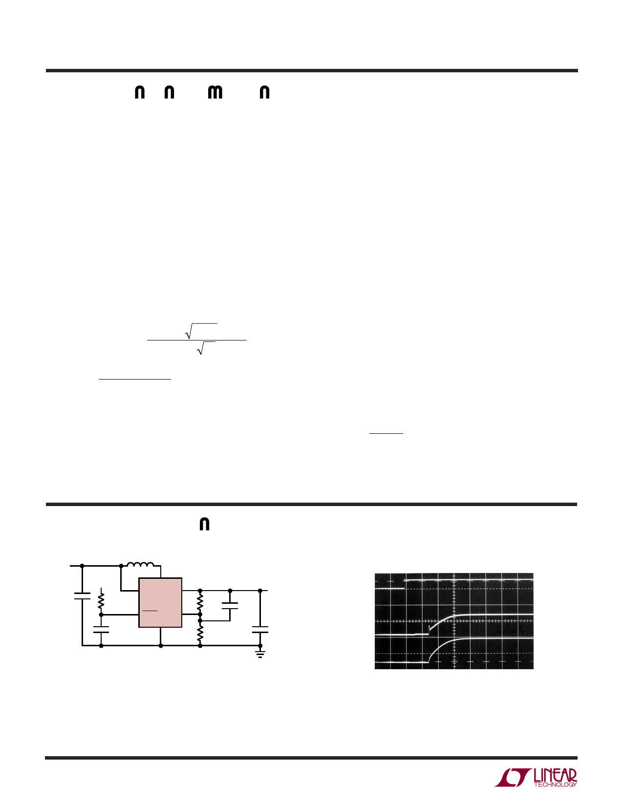
TYPICAL APPLICATIO S
VIN
5V
C1
1µF
L1
10µH
CONTROL
SIGNAL
47k
47nF
1
6
SW
5
VIN VOUT
LT3461A
4
3
SHDN FB
GND
2
R1
261k
R2
30.1k
15pF
VOUT
12V
70mA
C2
1µF
C1, C2: TAIYO YUDEN EMK212BJ105
L1: MURATA LQH32CN100K53
3461a TA02a
Figure 4. 5V to 12V with Soft-Start Circuit (LT3461A)
Input Current and Output Voltage
CONTROL
SIGNAL
5V/DIV
IIN
50mA/DIV
VOUT
5V/DIV
1ms/DIV
3461a TA02b
3461af
6
Share Link: 