LT1946A Ver la hoja de datos (PDF) - Linear Technology
Número de pieza
componentes Descripción
Fabricante
LT1946A Datasheet PDF : 12 Pages
| |||
LT1946A
APPLICATIO S I FOR ATIO
capacitor is sufficient for most applications, but systems
with very low output currents may need only a 1µF or
smaller output capacitor. Solid tantalum or OSCON ca-
pacitors can be used, but they will occupy more board area
than a ceramic and will have a higher ESR. Always use a
capacitor with a sufficient voltage rating.
Ceramic capacitors also make a good choice for the input
decoupling capacitor, which should be placed as close as
possible to the LT1946A. A 2.2µF to 4.7µF input capacitor
is sufficient for most applications. Table 2 shows a list of
several ceramic capacitor manufacturers. Consult the
manufacturers for detailed information on their entire
selection of ceramic parts.
Table 2. Ceramic Capacitor Manufacturers
Taiyo Yuden
(408) 573-4150
www.t-yuden.com
AVX
(803) 448-9411
www.avxcorp.com
Murata
(714) 852-2001
www.murata.com
Compensation
To compensate the feedback loop of the LT1946A, a series
resistor-capacitor network should be connected from the
COMP pin to GND. For most applications, a capacitor in the
range of 90pF to 470pF will suffice. A good starting value
for the compensation capacitor, CC, is 270pF. The com-
pensation resistor, RC, is usually in the range of 20k to
100k. A good technique to compensate a new application
is to use a 100k potentiometer in place of RC, and use a
270pF capacitor for CC. By adjusting the potentiometer
while observing the transient response, the optimum
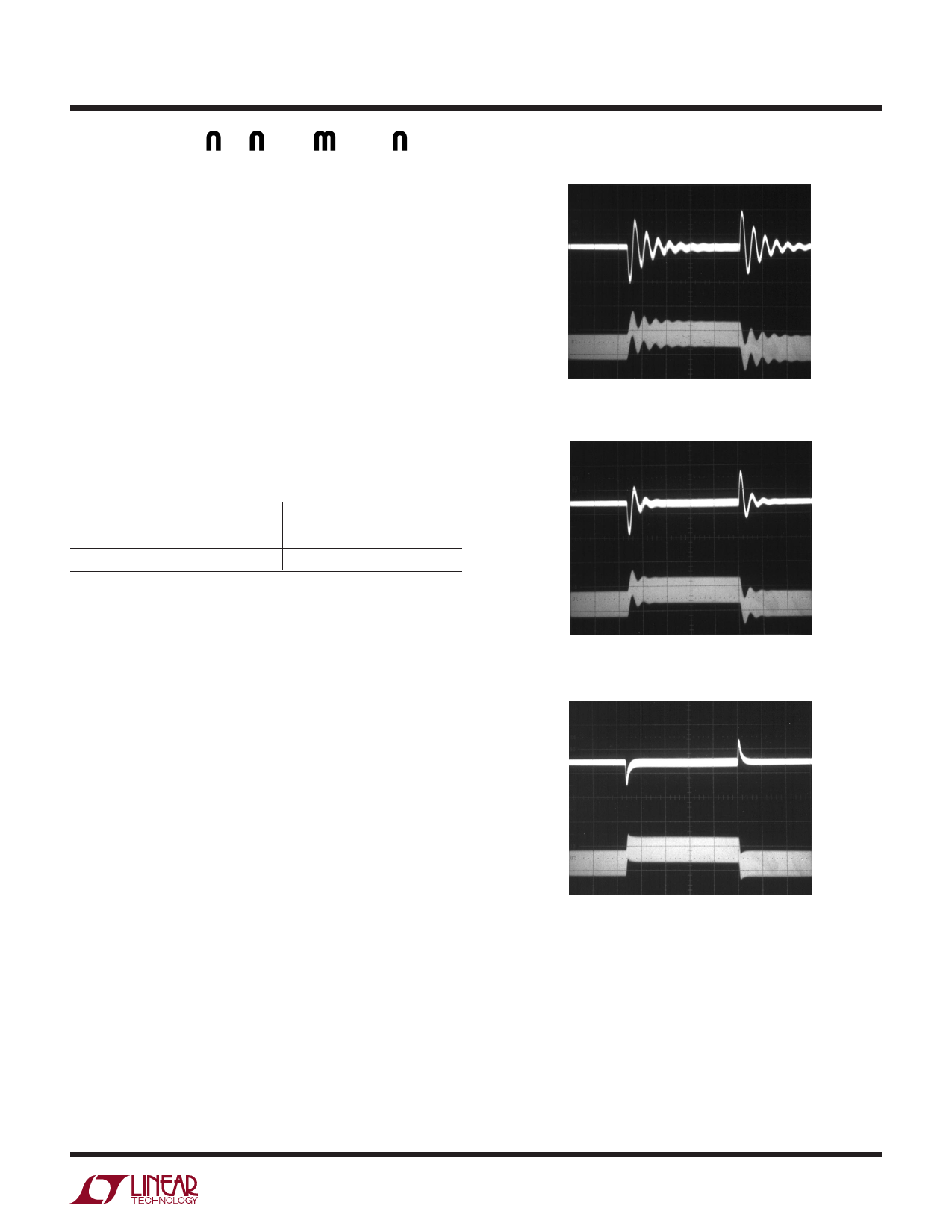
value for RC can be found. Figures 3a-3c illustrate this
process for the circuit of Figure 1. Figure 3a shows the
transient response with RC equal to 2.5k. The phase
margin is poor as evidenced by the excessive ringing in the
output voltage and inductor current. In Figure 3b the value
of RC is increased to 6.5k, which results in a more damped
response. Figure 3c shows the results when RC is in-
creased further to 27.4k. The transient response is nicely
damped and the compensation procedure is complete.
The COMP pin provides access to an internal resistor
(120k) and capacitor (90pF). For some applications, these
values will suffice and no external RC and CC will be
needed.
VOUT
200mV/DIV
AC COUPLED
IL1
0.5A/DIV
RC = 2.5k
50µs/DIV
1946A F03a
Figure 3a. Transient Response Shows Excessive Ringing
VOUT
200mV/DIV
AC COUPLED
IL1
0.5A/DIV
RC = 6.5k
50µs/DIV
1946A F03b
Figure 3b. Transient Response is Better
VOUT
200mV/DIV
AC COUPLED
IL1
0.5A/DIV
RC = 27.4k
50µs/DIV
1946A F03c
Figure 3c. Transient Response is Well Damped
Compensation-Theory
Like all other current mode switching regulators, the
LT1946A needs to be compensated for stable and efficient
operation. Two feedback loops are used in the LT1946A:
a fast current loop which does not require compensation,
and a slower voltage loop which does. Standard bode plot
analysis can be used to understand and adjust the voltage
feedback loop.
sn1946a 1946afs
7
Share Link: 