LT1946EMS8 Ver la hoja de datos (PDF) - Linear Technology
Número de pieza
componentes Descripción
Fabricante
LT1946EMS8 Datasheet PDF : 12 Pages
| |||
LT1946
APPLICATIO S I FOR ATIO
100
50
0
–50
100
0
1k
10k 25k 100k
FREQUENCY (Hz)
1M
1946 F05a
–100
60°
–180
–200
100
1k
10k 25k 100k
FREQUENCY (Hz)
1M
1946 F05b
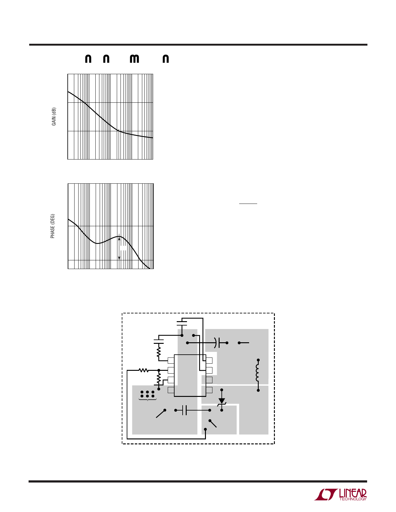
Figure 5. Bode Plot of Figure 1’s Circuit
Diode Selection
A Schottky diode is recommended for use with the LT1946.
The Microsemi UPS120 is a very good choice. Where the
input to output voltage differential exceeds 20V, use the
UPS140 (a 40V diode). These diodes are rated to handle an
average forward current of 1A. For applications where the
average forward current of the diode is less than 0.5A, an
ON Semiconductor MBR0520 diode can be used
Setting Output Voltage
To set the output voltage, select the values of R1 and R2
(see Figure 1) according to the following equation:
R1 =
R2⎛⎝⎜
VOUT
1.25V
–
1⎞⎠⎟
A good range for R2 is from 5k to 30k.
Layout Hints
The high speed operation of the LT1946 demands careful
attention to board layout. You will not get advertised
performance with careless layout. Figure 6 shows the
recommended component placement for a boost
converter.
GROUND PLANE
CSS
C1
CC
+
VIN
RC
1
8
R1
2
7
LT1946
L1
R2
3
6
SHUTDOWN
4
5
MULTIPLE
VIAs
GND
C2
VOUT
1946 F06
Figure 6. Recommended Component Placement for Boost Converter. Note Direct High Current Paths Using Wide PC Traces. Minimize
Trace Area at Pin 1 (VC) and Pin 2 (FB). Use Multiple Vias to Tie Pin 4 Copper to Ground Plane. Use Vias at One Location Only to Avoid
Introducing Switching Currents Into the Ground Plane
1946fb
8
Share Link: 