LT1946EMS8 Ver la hoja de datos (PDF) - Linear Technology
Número de pieza
componentes Descripción
Fabricante
LT1946EMS8 Datasheet PDF : 12 Pages
| |||
LT1946
APPLICATIO S I FOR ATIO
Capacitor Selection
Low ESR (equivalent series resistance) capacitors should
be used at the output to minimize the output ripple voltage.
Multilayer ceramic capacitors are an excellent choice, as
they have an extremely low ESR and are available in very
small packages. X5R or X7R dielectrics are preferred, as
these materials retain the capacitance over wide voltage
and temperature ranges. A 4.7µF to 20µF output capacitor
is sufficient for most applications, but systems with very
low output currents may need only a 1µF or 2.2µF output
capacitor. Solid tantalum or OS-CON capacitors can be
used, but they will occupy more board area than a ceramic
and will have a higher ESR. Always use a capacitor with a
sufficient voltage rating.
Ceramic capacitors also make a good choice for the input
decoupling capacitor, which should be placed as close as
possible to the LT1946. A 2.2µF to 4.7µF input capacitor is
sufficient for most applications. Table 2 shows a list of
several ceramic capacitor manufacturers. Consult the
manufacturers for detailed information on their entire
selection of ceramic parts.
Table 2. Ceramic Capacitor Manufacturers
Taiyo Yuden
(408) 573-4150
www.t-yuden.com
AVX
(803) 448-9411
www.avxcorp.com
Murata
(714) 852-2001
www.murata.com
Compensation—Adjustment
To compensate the feedback loop of the LT1946, a series
resistor-capacitor network should be connected from the
COMP pin to GND. For most applications, a capacitor in
the range of 220pF to 680pF will suffice. A good starting
value for the compensation capacitor, CC, is 470pF. The
compensation resistor, RC, is usually in the range of 20k
to 100k. A good technique to compensate a new applica-
tion is to use a 100kΩ potentiometer in place of RC, and
use a 470pF capacitor for CC. By adjusting the potentiom-
eter while observing the transient response, the optimum
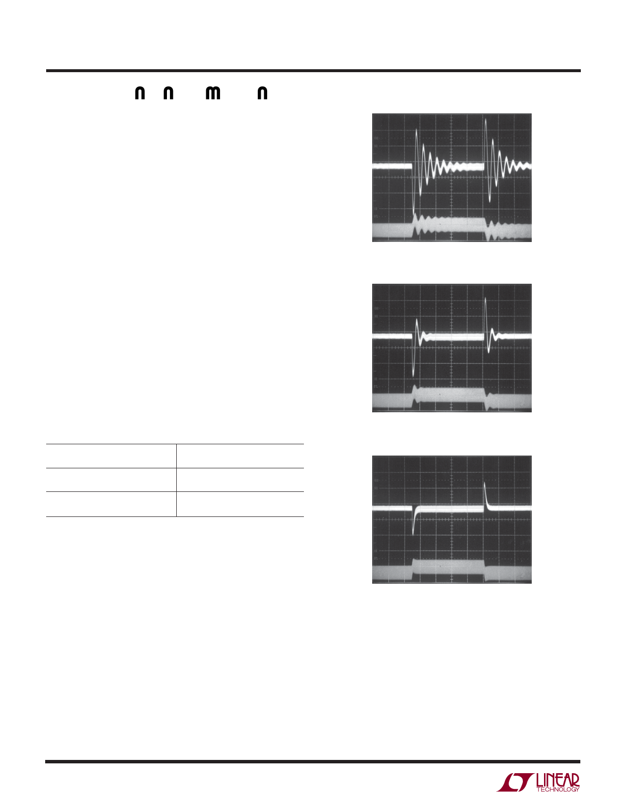
value for RC can be found. Figures 3a to 3c illustrate this
process for the circuit of Figure 1 with a load current
stepped from 250mA to 300mA. Figure 3a shows the tran-
sient response with RC equal to 7.5k. The phase margin is
6
VOUT
20mV/DIV
AC COUPLED
ILI
0.5A/DIV
AC COUPLED
RC = 7.5k
200µs/DIV
1946 F03a
Figure 3a. Transient Response Shows Excessive Ringing
VOUT
20mV/DIV
AC COUPLED
ILI
0.5A/DIV
AC COUPLED
RC = 18k
200µs/DIV
1946 F03b
Figure 3b. Transient Response is Better
VOUT
20mV/DIV
AC COUPLED
ILI
0.5A/DIV
AC COUPLED
RC = 49.9k
200µs/DIV
1946 F03b
Figure 3c. Transient Response is Well Damped
poor as evidenced by the excessive ringing in the output
voltage and inductor current. In Figure 3b, the value of RC
is increased to 18k, which results in a more damped re-
sponse. Figure 3c shows the results when RC is increased
further to 49.9k. The transient response is nicely damped
and the compensation procedure is complete. The COMP
pin provides access to an internal resistor (120k) and
capacitor (90pF). For some applications, these values will
suffice and no external RC and CC will be needed.
1946fb
Share Link: 