LT1239 Ver la hoja de datos (PDF) - Linear Technology
Número de pieza
componentes Descripción
Fabricante
LT1239 Datasheet PDF : 12 Pages
| |||
LT1239
APPLICATIONS INFORMATION
Using the Current Monitor Function
The current monitor pin outputs a current proportional to
the output current of the regulator. Both regulator 1 and
regulator 2 have independent current monitor pins. The
current monitor function can be used to monitor charge in
the backup cells, to set up a constant current output or to
adjust the current limit of the regulator. The current
monitor pin should be tied to the output pin if the current
monitor function is not used. This will minimize quiescent
current.
The current output of the current monitor pin can be
converted to a voltage by feeding the current monitor pin
output current through a resistor. The voltage across the
resistor will be proportional to output current. This signal
can be used to monitor the output current for either
regulator. Regulator 1 output current is equal to the charge
current for the backup batteries plus the load current of
regulator 2. If regulator 1 output current is greater than
regulator 2 output current, the difference between the
currents is the charge current for the backup cells. If
regulator 2 output current is greater than regulator 1
output current, the difference between the currents is the
discharge current for the backup cells. By integrating the
difference between regulator 1 output current and regula-
tor 2 output current the total charge in the backup cells can
be determined.
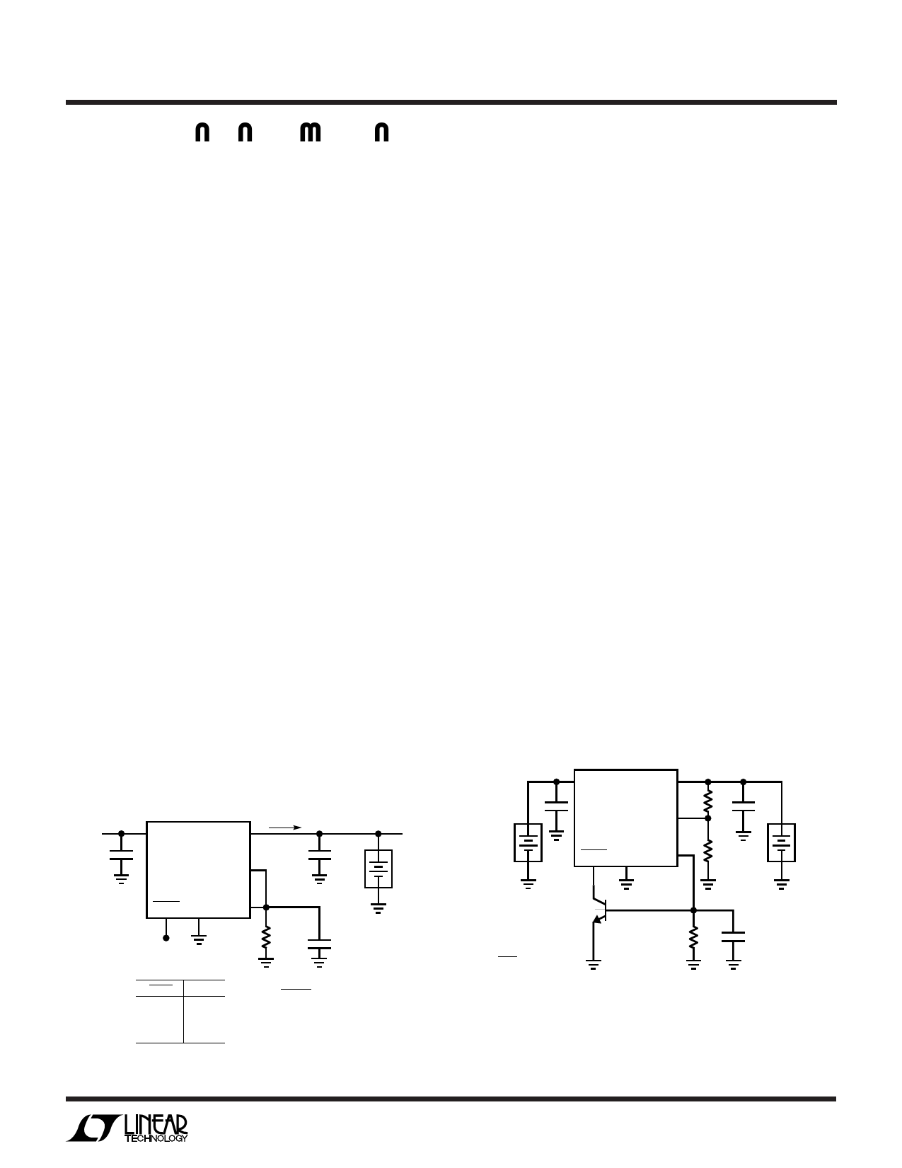
Constant Current Charging
NiCd backup batteries are normally charged with a con-
stant current trickle charge. This can be accomplished
7-24V
+
IN 1
OUT 1
LT1239 IMON1
SHDN1 GND ADJ
ICHARGE
+
10µF
(3.75V)
NiCd
BACKUP
BATTERY
R1
+
2µF
VSHDN1
< 0.25V
> 2.8V
NC
ICHARGE
OFF
ON
ON
R1
=
3.75V
ICHARGE
×
220
Figure 3. Constant Current Charging
LT1239 • F03
using regulator 1 and the circuit shown in Figure 3.
In this circuit the voltage at the adjust pin is proportional
to the output current. Regulator 1 will servo its output to
force 3.75V at the adjust pin. The output current will be
scaled from the current monitor pin current by a ratio of
220:1. Output current is equal to 220 × current monitor pin
current. The output current is set by choosing resistor R1,
in the formula shown in Figure 3. Regulator 1 will source
a constant current as long as the voltage at its input is
greater than the battery voltage plus the dropout voltage of
regulator 1. External power monitoring circuitry can be
used to shutdown regulator 1 to terminate charge when a
low current sleep mode is desired.
Setting Current Limit Using the Current Monitor Pin
With the addition of some simple external circuitry the
current monitor pin can be used to control the output
short-circuit current of the regulator. As shown in Figure
4, the current monitor pin can be tied to ground through
a resistor to generate a voltage proportional to output
current. When the voltage across R3 is equal to approxi-
mately 0.6V (one VBE) Q1 will turn on and pull down on the
shutdown pin of the regulator. Q1 effectively steals drive
current from the regulator to limit the output current. C1
is needed to roll off the gain of Q1. Current limit can be set
using the formula shown in Figure 4. This circuit can be
used with either regulator. The shutdown function can
also be used. An open-collector gate connected in parallel
with Q1 can shut down the regulator.
MAIN
BATTERIES
IN 1
+
OUT 1
LT1239 ADJ
SHDN2 GND IMON1
R2 + 10µF
NiCd
R1
BACKUP
BATTERY
R3 =
0.6V
ILIM
×
220
Q1
2N3904
+ C1
R3
2µF
LT1239 • F04
Figure 4. Reducing Current Limit
Using the Comparator
The comparator in the LT1239 is intended to be used as an
automatic switchover circuit between the main 5V
9
Share Link: 