TC1263 Ver la hoja de datos (PDF) - Microchip Technology
Número de pieza
componentes Descripción
Fabricante
TC1263 Datasheet PDF : 14 Pages
| |||
4.0 THERMAL CONSIDERATIONS
4.1 Thermal Shutdown
Integrated thermal protection circuitry shuts the
regulator off when die temperature exceeds 160°C.
The regulator remains off until the die temperature
drops to approximately 150°C.
4.2 Power Dissipation
The amount of power the regulator dissipates is
primarily a function of input and output voltage, and
output current. The following equation is used to
calculate worst case actual power dissipation:
EQUATION 4-1:
PD ≈ (VINMAX – VOUTMIN)ILOADMAX
Where:
PD = Worst case actual power dissipation
VINMAX = Maximum voltage on VIN
VOUTMIN = Minimum regulator output voltage
ILOADMAX = Maximum output (load) current
The maximum allowable power dissipation (Equation
4-2) is a function of the maximum ambient temperature
(TAMAX), the maximum allowable die temperature
(TJMAX) and the thermal resistance from junction-to-air
(θJA).
EQUATION 4-2:
PDMAX = (TJMAX – TAMAX)
θJA
Where all terms are previously defined.
Table 4-1 and Table 4-2 show various values of θJA for
the TC1263 packages.
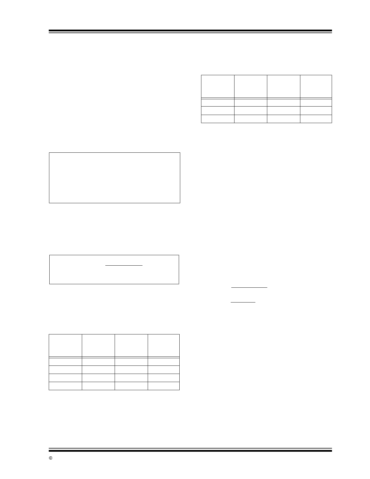
TABLE 4-1:
THERMAL RESISTANCE
GUIDELINES FOR TC1263 IN
8-PIN SOIC PACKAGE
Copper
Area
(Topside)*
Copper
Area
(Backside)
Board
Area
Thermal
Resistance
(θJA)
2500 sq mm 2500 sq mm 2500 sq mm 60°C/W
1000 sq mm 2500 sq mm 2500 sq mm 60°C/W
225 sq mm 2500 sq mm 2500 sq mm 68°C/W
100 sq mm 2500 sq mm 2500 sq mm 74°C/W
*Pin 2 is ground. Device is mounted on topside.
TC1263
TABLE 4-2:
THERMAL RESISTANCE
GUIDELINES FOR TC1263 IN
3-PIN TO-220/DDPAK
PACKAGE
Copper
Area
(Topside)*
Copper
Area
(Backside)
Board
Area
Thermal
Resistance
(θJA)
2500 sq mm 2500 sq mm 2500 sq mm 25°C/W
1000 sq mm 2500 sq mm 2500 sq mm 27°C/W
125 sq mm 2500 sq mm 2500 sq mm 35°C/W
*Tab of device attached to topside copper
Equation 4-1 can be used in conjunction with Equation
4-2 to ensure regulator thermal operation is within
limits. For example:
Given:
VINMAX = 3.3V ± 10%
VOUTMIN = 2.7V ± 0.5%
ILOADMAX = 275mA
TJMAX = 125°C
TAMAX = 95°C
θJA
= 60°C/W
Find: 1. Actual power dissipation
2. Maximum allowable dissipation
Actual power dissipation:
PD ≈ (VINMAX – VOUTMIN)ILOADMAX
= [(3.3 x 1.1) – (2.7 x .995)]275 x 10–3
= 260mW
Maximum allowable power dissipation:
PDMAX = (TJMAX – TAMAX)
θJA
= (125 – 95)
60
= 500mW
In this example, the TC1263 dissipates a maximum of
260mW; below the allowable limit of 500mW. In a
similar manner, Equation 4-1 and Equation 4-2 can be
used to calculate maximum current and/or input
voltage limits. For example, the maximum allowable
VIN, is found by substituting the maximum allowable
power dissipation of 500mW into Equation 4-1, from
which VINMAX = 4.6V.
© 2002 Microchip Technology Inc.
DS21374B-page 5
Share Link: 