LR38637 Ver la hoja de datos (PDF) - Sharp Electronics
Número de pieza
componentes Descripción
Fabricante
LR38637 Datasheet PDF : 15 Pages
| |||
LR38637
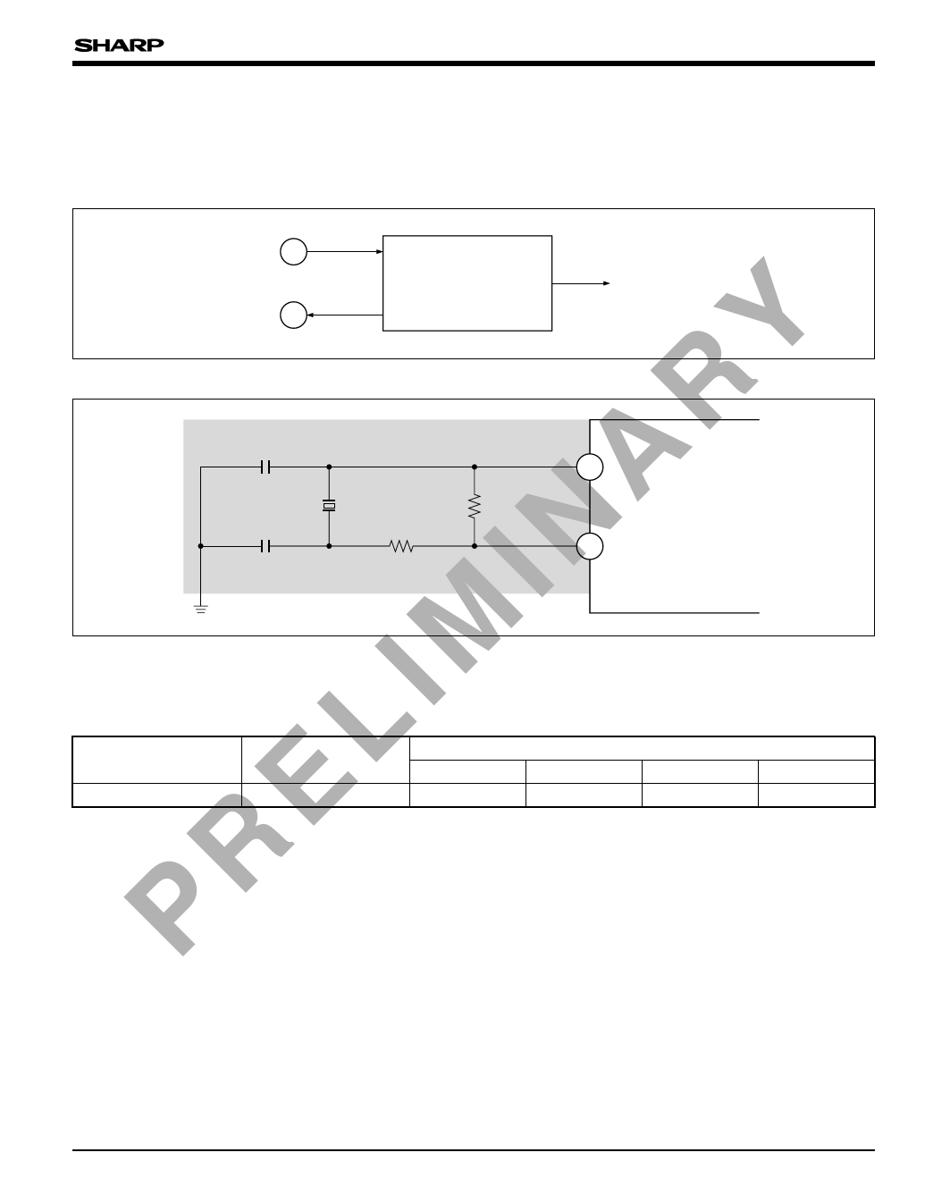
FUNCTIONAL DESCRIPTION
Oscillation Circuit
Oscillation circuit leads the same frequency of the
quartz crystal connected to I/O pins and provides
the same frequency to the internal logic circuits as
shown in Fig. 1 and Fig. 2.
CKI
CKO
C1
C2
Oscillation Circuit
(I/O Buffer)
To Internal Logic
Y Fig. 1 Block Diagram of Oscillation Circuit
I N A R RD1
RD2
CKI
CKO
Fig. 2 Clock Input to Oscillation Circuit
I M Connection of Quartz Crystal (TA = –20 to +70˚C, DVDD2 = 2.7 to 3.6 V, DVDD = 2.25 to 2.75 V) :
Example of Oscillation under Fundamental Frequencies
L APPLICABLE PINS
CKI, CKO
FUNDAMENTAL
FREQUENCY [MHz]
24.5454 or 9.0000
C1 [pF]
10
RECOMMENDED COEFFICIENT
C2 [pF]
RD1 [$]
10
220
RD2 [$]
1M
E NOTES :
1. The oscillation circuit should be located as close to CKI, CKO as possible.
2. Do not install other signal lines in the shaded area.
3. Perform due evaluation on the match between the LR38637 and the quartz crystal.
R Clock
P Input clock from the CKI pin is supplied to CMOS
Power ON/OFF Sequence
Two power supplies are used with the LR38637.
image sensor through the SCKO pin after dividing One (DVDD2) is used for I/O buffer and the other
according to inside parameter of the LR38637.
(DVDD) is used for the core logic circuits.
Set the EXTCLK pin to open or "High level".
Power ON : Be sure to turn ON the internal power
The clock frequency which can be inputted to the
of DVDD first.
CKI input pin is 24.5454 MHz or 9 MHz.
Power OFF : Be sure to turn OFF the I/O buffer of
DVDD2 first.
8
Share Link: 