LMB10S(2013) Ver la hoja de datos (PDF) - Micro Commercial Components
Número de pieza
componentes Descripción
Fabricante
LMB10S
(Rev.:2013)
(Rev.:2013)
Micro Commercial Components

LMB10S Datasheet PDF : 3 Pages
| |||
MCC
TM
Micro Commercial Components
omponents
20736 Marilla Street Chatsworth
!"#
$%
!"#
LMB2S
THRU
LMB10S
Features
• Low Profile: Typical height of 1.4mm
• High Temperature Soldering Guaranteed:260oC/10 Second
• High surge current capability
• Halogen free available upon request by adding suffix "-HF"
• Epoxy meets UL 94 V-0 flammability rating
• Moisture Sensitivity Level 1
• Lead Free Finish/Rohs Compliant (Note1) ("P"Suffix designates
Compliant. See ordering information)
Mechanical Data
• Terminals:Matte tin plated leads, solderable per J-STD-002B
and JESD22-B102D
1.0 Amp Single Phase
Glass Passivated
Bridge Rectifier
200 to 1000 Volts
LMBS -1
A
MCC
Part
Number
LMB2S
LMB4S
LMB6S
LMB8S
LMB10S
Device
Marking
LB2S
LB4S
LB6S
LB8S
LB10S
Maximum
Recurrent
Peak Reverse
Voltage
200V
400V
600V
800V
1000V
Maximum
RMS
Voltage
140V
280V
420V
560V
700V
Maximum
DC
Blocking
Voltage
200V
400V
600V
800V
1000V
C
E
B
D
F
G
H
J
Electrical Characteristics @ 25OC Unless Otherwise Specified K
Average Forward
Current
IF(AV)
1.0 A
0.8 A
on aluminum substrate
on glass-epoxy P.C.B
Peak Forward Surge IFSM
Current
30A 8.3ms, half sine
Maximum
Instantaneous
VF
0.95V IFM = 0.4A;
Forward Voltage
TA = 25OC
Maximum DC
Reverse Current At
IR
5uA
TA = 25�OC
Rated DC Blocking
500uA
TA = 125�OC
C
D
Voltage
Typical Thermal
RthJA 80�OC/W
Note 2
Resistance
R thJL 25�OC/W
L
Rating For Fusing
I2t
3.0A2s t<8.30ms
M
Operating Junction
and Storage
Temperature Range
TJ
TSTG
-55to+150
�OC
Notes: 1. High Temperature Solder Exemption Applied, see EU Directive Annex Notes 7
2. Device mounted P.C.B with 0.47x0.47''(12mmx12mm) Copper Pads.
L
M
.197
.205
.024
----
.024
----
.059
.032
.189
.150
.165
----
.209
.236
.252
.177
.185
.0009
.004
.006
.012
.017
.019
4.90
5.20
0.6
----
0.60
----
3.80
----
1.50
0.80
4.80
4.20
5.30
6.00
4.30
0.02
0.15
6.60
4.70
0.21
0.30
0.25
0.70
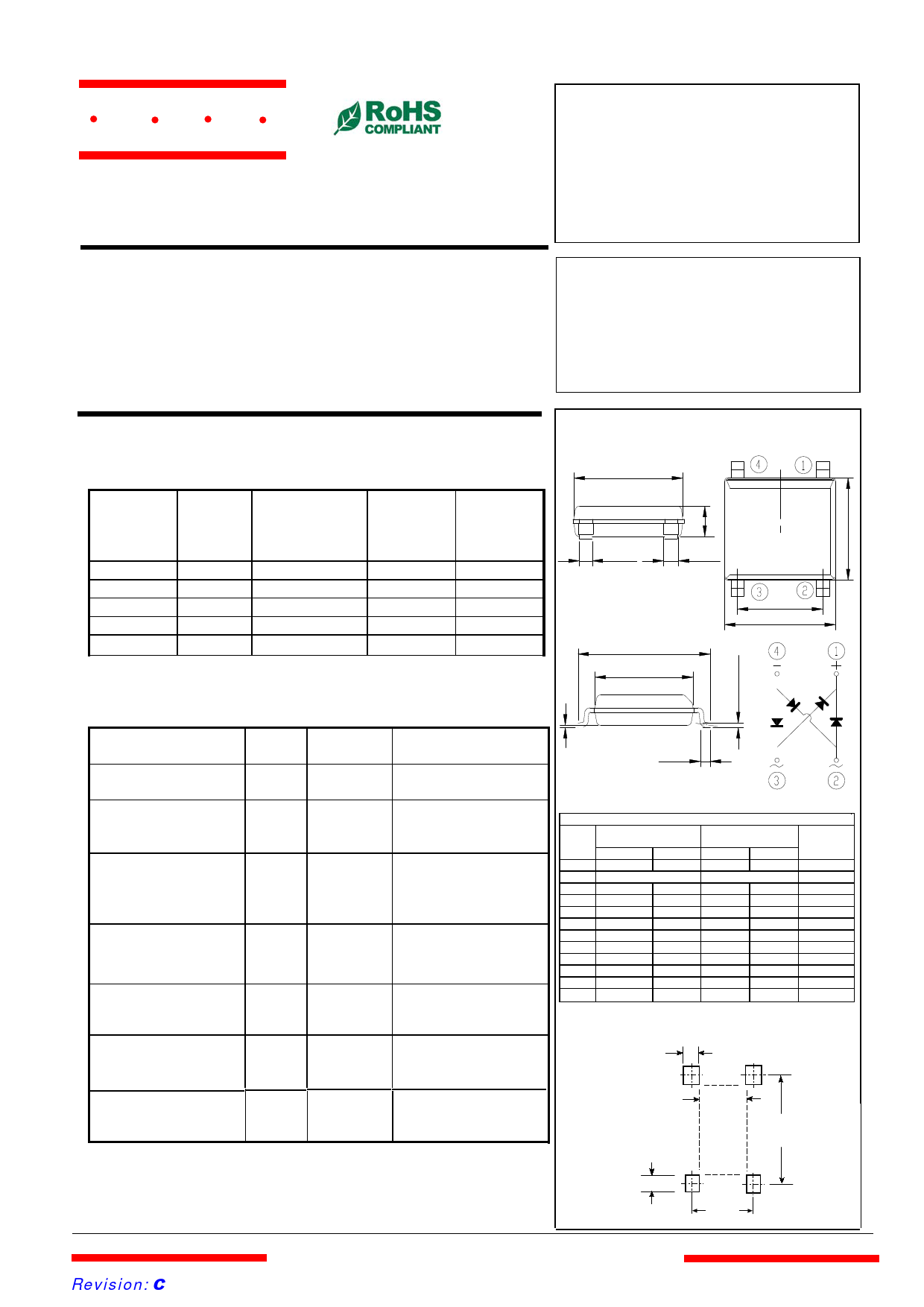
Mounting Pad Layout
0.036"
(0.9 mm)
0.060"
(1.5mm)
0.126"
(3.2mm)
0.225"
(5.72mm)
Revision: B
0.161"
(4.1mm)
www.mccsemi.com
1 of 3
2013/01/01
Share Link: