LAG639D Ver la hoja de datos (PDF) - Mitsumi
Número de pieza
componentes Descripción
Fabricante
LAG639D Datasheet PDF : 8 Pages
| |||
MITSUMI
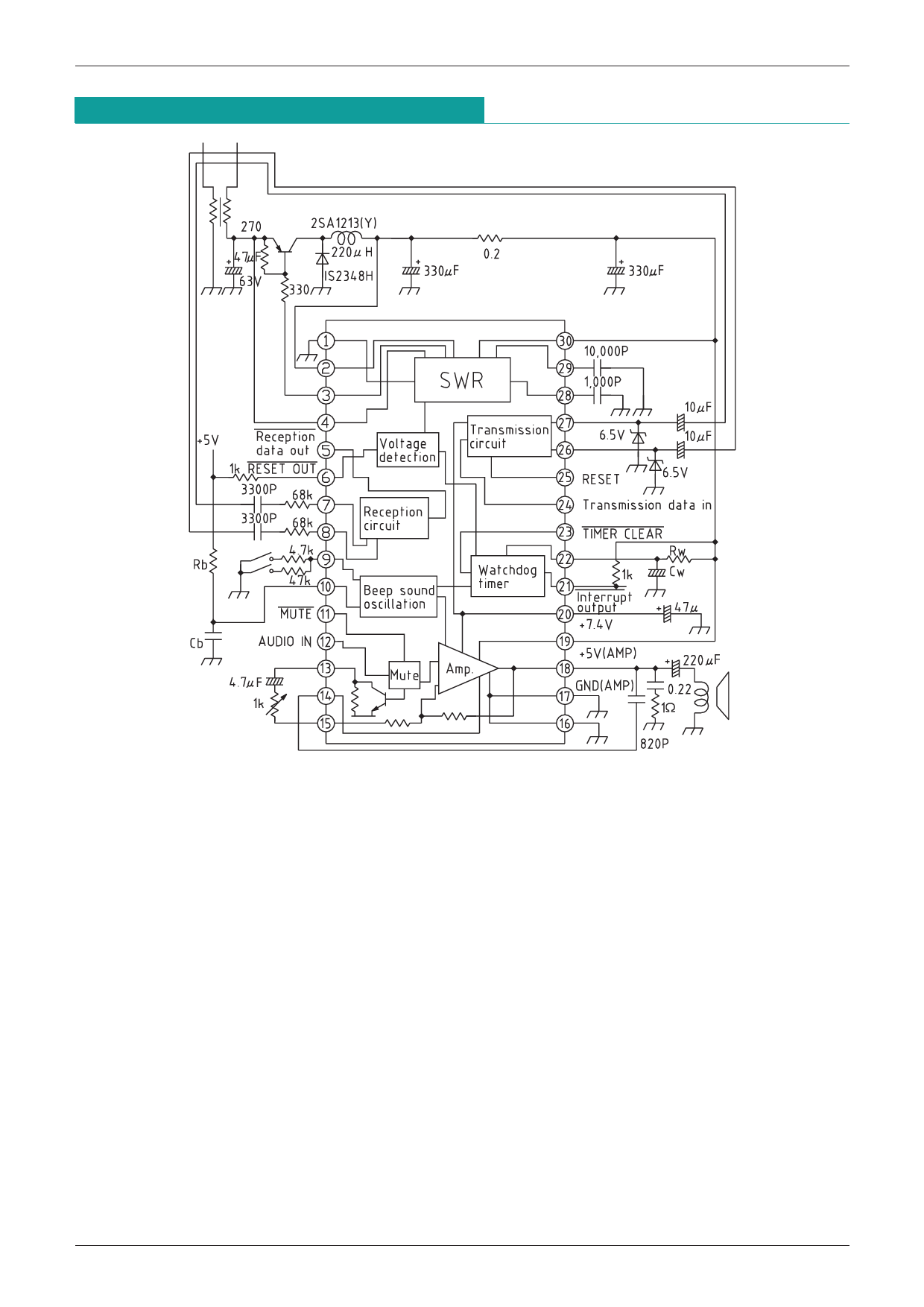
Block Diagram and Application Circuits
IC for Multifunction Telephones LAG639
1. The watchdog timer time is determined by the values of Rw and Cw.
Tt .=. Rw•Cw where Rw is 56kΩ to 560kΩ
Cw is between 0.01µF and 10µF
2. The beep sound frequency is determined by Rb and Cb.
Fb =.. 1/Rb•Cb where Rb is 56 kΩ to 330kΩ
Cb is between 4700PF and 22,000PF.
3. The beep sound volume can be varied through the resistance connected to pin 10. At 4.7kΩ the
voltage is approx. 4VP-P, and at 47kΩ it is about 0.4VP-P.
4. In overload protection operation the voltage across pins 1 to 30 is tested, with a limit of 100 ±20mV.
On load shorting, the test voltage is dropped to about 1/4 to conserve power.
Share Link: 