LA76850 Ver la hoja de datos (PDF) - SANYO -> Panasonic
Número de pieza
componentes Descripción
Fabricante
LA76850 Datasheet PDF : 31 Pages
| |||
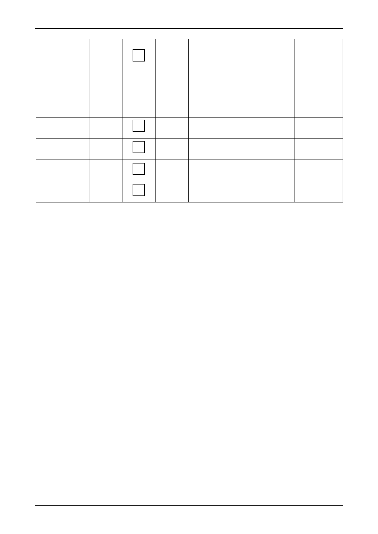
Continued from preceding page.
Input signal
Symbol
APC pull-in
range (U), (L)
fPU, fPL
NT Trap1 (4.5MHz),
2 (4.8MHz)
BG Trap1 (5.5MHz),
2 (5.85MHz)
I Trap1 (6.0MHz)
2 (6.55MHz)
DK Trap1 (6.5MHz)
NTR1
NTR2
BTR1
BTR2
ITR1
ITR2
DTR1
LA76850
Test point
29
29
29
29
29
Input signal
SG4
80dBµ
SG7
SG7
SG7
SG7
Test method
Connect an oscilloscope to pin 29 and adjust the
SG4 frequency to a frequency higher than
38.9MHz to bring the PLL into unlocked mode.
(A beat signal appears.) Lower the SG4 frequency
and measure the frequency at which the PLL locks
again. In the same manner, adjust the SG4
frequency to a lower frequency to bring the PLL
into unlocked mode. Higher the SG4 frequency
and measure the frequency at which the PLL locks
again.
Determine the output level difference between
carrier frequencies of 1Mhz, 4.5MHz and 4.8MHz.
(Reference:1MHz)
Determine the output level difference between
carrier frequencies of 1Mhz, 5.5MHz and
5.85MHz. (Reference:1MHz)
Determine the output level difference between
carrier frequencies of 1MHz, 6.0MHz and
6.55MHz. (Reference:1MHz)
Determine the output level difference between
carrier frequencies of 1MHz and 6.5MHz.
(Reference:1MHz)
Bus conditions
SIF.SYS = "00"
SIF.SYS = "01"
SIF.SYS = "10"
SIF.SYS = "11"
NoA0017-10/31
Share Link: 