LA75503V Ver la hoja de datos (PDF) - SANYO -> Panasonic
Número de pieza
componentes Descripción
Fabricante
LA75503V Datasheet PDF : 15 Pages
| |||
LA75503V
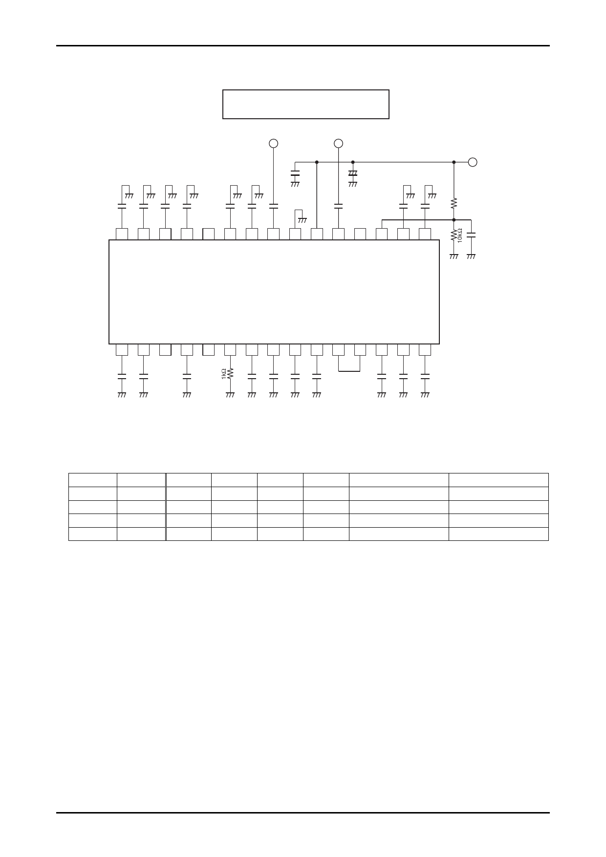
Test circuit 2
Input Impedance Measuring Circuit (VIF, First SIF input impedance)
Impedance analyzer
VIF INPUT 1st SIF INPUT
+
100µF
30 29 28 27 26 25 24 23 22 21 20 19 18 17 16
VCC
15kΩ
LA75503V
1 2 3 4 5 6 7 8 9 10 11 12 13 14 15
Top View
System Switching
• SIF system switch
The SIF system is switched by setting pins A (pin 13) and B (pin 14) to GND or OPEN.
A
B
B/G
I
D/K
M/N
GND
GND
{
GND
OPEN
{
OPEN
GND
{
OPEN
OPEN
{
FM DET LEVEL
De-emphasis
6dB
75µs
0dB
50µs
0dB
50µs
0dB
50µs
Note: "{" indicates that the system is selected.
• IF system switch
38.9MHz is selected as the IF frequency by leaving pin 15 (crystal oscillation) open. 38MHz is selected by adding
220kΩ between pin 15 and GND. This device can also select 39.5MHz operation by adding a 220kΩ resistor between
pin 15 and VCC.
• Split/inter carrier switch
Inter carrier is selected by setting the first SIF input (pin 20) to GND.
Sound Trap
The trapping point of the sound trap is set approximately 250kHz above the SIF center frequency of each mode to
improve the video S/N. Therefore, design using split specifications is preferable.
No.6804-6/15
Share Link: 