LA4635A Ver la hoja de datos (PDF) - SANYO -> Panasonic
Número de pieza
componentes Descripción
Fabricante
LA4635A Datasheet PDF : 3 Pages
| |||
LA4635A
Operating Characteristics at Ta = 25°C, VCC = 12 V, RL = 3 Ω, f = 1 kHz, Rg = 600 Ω
Parameter
Quiescent current
Standby current
Voltage gain
Total harmonic distortion
Output power
Output noise voltage
Ripple rejection
Channel separation
Input resistance
Standby pin voltage
Symbol
ICCO
Ist
VG
THD
PO1
PO2
VNO
SVRR
CH Sep
Ri
VST
Rg = 0
Conditions
VO = 0 dBm
PO = 1 W
THD = 10%
VCC = 9 V, THD = 10%
Rg = 0, BPF = 20 Hz to 20 kHz
Rg = 0, fR = 100 Hz, VR = 0 dBm
Rg = 10 kΩ, VO = 0 dBm
Amplifier on (pin 5 voltage)
Ratings
min
typ
max Unit
18
35
80 mA
1
10
µA
33
35
37 dB
0.15
0.4
%
3.0
4.5
W
2.0
2.5
W
0.05
0.25 mV
50
60
dB
55
65
dB
20
30
40
kΩ
1.5
5.0
V
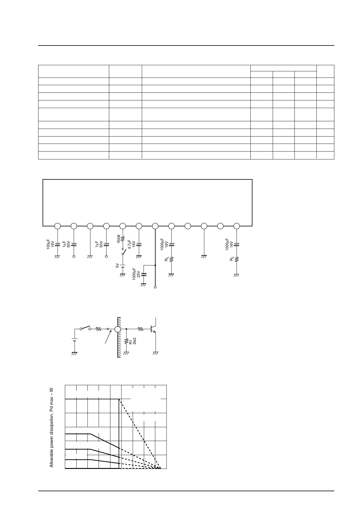
Sample Application Circuit
LA4635A
(Popping Noise
(Ripple Filter)
PRE
Eliminator)
PWR
DC
IN1
GND
IN2 STBY P.P
VCC OUT2 NC
GND
NC OUT1
1
2
3
4
5
6
7
8
9
10
11
12
+
+
+
+
+
+
+
VCC
Top view
ILA00778
* If voltage is to be
applied to the Standby
pin (pin 5), a resistor
(Rx) should be
inserted to limit the
inflow current, as
required. Please refer
to the information
below.
(Reference) Pin 5 Equivalent Circuit Inside IC
Standby +
Pin Voltage
Vx
Rx Ix
R2
STBY 2kΩ
5
Ix=max 4.5mA
ILA00779
Pd max -- Ta
30
Infinite heat sink
25
20
AI heat sink
Mounting
torque 39N•cm
Flat washer
Silicone grease
applied
qjc=3°C / W
15
100 ¥ 100 ¥ 1.5 mm3
12.5
10
50 ¥ 50 ¥ 1.5 mm3
7
5 Single IC
3.2
0
--20 0
20 40 60 80 100 120 140 160
Ambient temperature, Ta – °C
ILA00777
• The amplifier can be turned on and off by controlling
the level (high/low) of pin 5.
• Applying a signal equal or greater than 1.5 V and
800 µA to pin 5 turns on the amplifier. (If 5 V is applied
directly to pin 5 the inflow current of pin 5 is approxi-
mately 4.5 mA.)
• If a voltage, Vx, exceeding 5 V is to be applied, current
limiting resistor (Rx) should be inserted to limit the
inflow current to 4.5 mA. (See following equation.)
Rx = (Vx – 5 V) / 4.5 mA
• If pin 5 is to be controlled by the microprocessor, the
pin 5 inflow current (Ix) should be optimized for the
capacity of the microprocessor by calculating Rx using
the following equation, as a general guideline, and then
confirming the inflow current through actual measure-
ment.
Rx = (Vx / Ix) – R1 (2 kΩ)
Note: The LA4635A is basically pin-compatible with the
LA4636, but there are partial differences in
operation and usage, including with regard to
externally connected parts.
No. 6983-2/3
Share Link: 