L9942 Ver la hoja de datos (PDF) - STMicroelectronics
Número de pieza
componentes Descripción
Fabricante
L9942 Datasheet PDF : 40 Pages
| |||
L9942
Device description
slow decay mode always. Otherwise one of the fast decay modes is automatic selected for a
quick decrease of the load current and so it obtains new lower target value.
2.10
Overcurrent detection
The overcurrent detection circuit monitors the load current in each activated output stage. In
HS stage it is in function after detection of current limit during PWM cycle and in LS stage it
works permanently. If the load current exceeds the overcurrent detection threshold for at
least tISC = 4 µs, the overcurrent flag is set and the corresponding driver is switched off to
reduce the power dissipation and to protect the integrated circuit. Error condition is latched
and the microcontroller needs to clear the status bits to reactivate the drivers.
2.11
Open load detection
The open load detection monitors the activity time of the PWM controller and is available for
each phase. If the limit of load current is below around 100mA then open load condition is
detectable. Open load bit for a bridge is set in the register6 if this low current limit can't
reached after at least 15 consecutive PWM cycles.
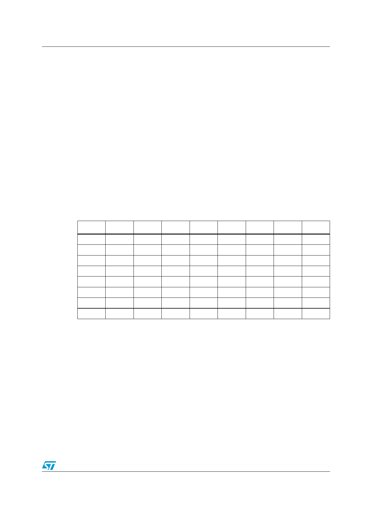
Table 3. Truth table
DC2
DC1
DC0
I4
I3
I2
I1
I0 max. IOL
0
0
0
0
x
x
x
x
46mA
0
0
1
0
x
x
x
x
68mA
0
1
0
0
0
x
x
x
52mA
0
1
1
0
0
x
x
x
81mA
1
0
0
0
0
0
x
x
53mA
1
0
1
0
0
0
x
x
78mA
1
1
0
0
0
0
0
1
37mA
1
1
1
0
0
0
0
1
44mA
Truth table shows possible profiles for active open load detection. Maximum threshold IOL is
shown in left column if x bits are 1 (see also Figure 7). Lowest possible limit is e.g. 3.1 mA
for DC2=DC1=DC0=0 and it is set only I0=1.
2.12
Stepping modes
One full revolution can consist of four full steps, eight half steps, sixteen mini steps or 32
microsteps.
Mode is set up in register 0 and it defines increment size of phase counter. Phase counter
value defines address of corresponding current profile. Stepping modes with typical profile
values can see in Figure 3 (e.g. also so called 'Two Phase On' shown in dashed line).
Doc ID 11778 Rev 7
11/40
Share Link: 