L9907 Ver la hoja de datos (PDF) - STMicroelectronics
Número de pieza
componentes Descripción
Fabricante
L9907 Datasheet PDF : 8 Pages
| |||
L9907N
FUNCTIONAL DESCRIPTION
The L9907N is a power comparator with full-
bridge push-pull outputs, intended for driving a
DC motor in the headling adjustment system.
The basic function of the device is shown in the
input-output tranfer characteristic, Fig. 1.
For differential input voltage (VINC - VINF) lower
than the negative NEUTRAL ZONE threshold, VN-
the output voltage is negative (corresponds to
motor direction right), for increasing differential in-
put voltage, this status changes to the zero output
voltage (motor is actively braked), when the differ-
ential input voltage exceeds the VST- stop range
threshold. The output status remains in this condi-
tion as long as the differential input voltage re-
mains within the NEUTRAL ZONE. If the input
voltage increases above the positive NEUTRAL
ZONE threshold VN+, the output voltage become
positive (motor direction left).
Similar behaviour is obtained for decreasing the
input voltage. The output status transitions are
marked with the arrows showing the correspond-
ing direction of the output status variation. The
active braking mode is got with both outputs in
"HIGH" status
The above described behaviour assures high po-
sitioning precision, corresponding to the STOP
RANGE and high noise immunity in the adjusted
condition due to the NEUTRAL ZONE hysteresis
thresholds .
Both the above described thresholds are defined
referring to INC, INF pins. The error due to voltage
drop over the input signal source resistances
RINC, RINF is minimized with extremely low input
bias currents IINC, IINF.
The above mentioned resistors (RINC, RINF) are
necessary for the input current limitation during
the transients on the VBAT line. The input source
resistors must be dimensioned so that in case of
a line transient the input current in the input pin,
clamped with the internal input protection diodes
do not increase over the specified absolute maxi-
mum value.
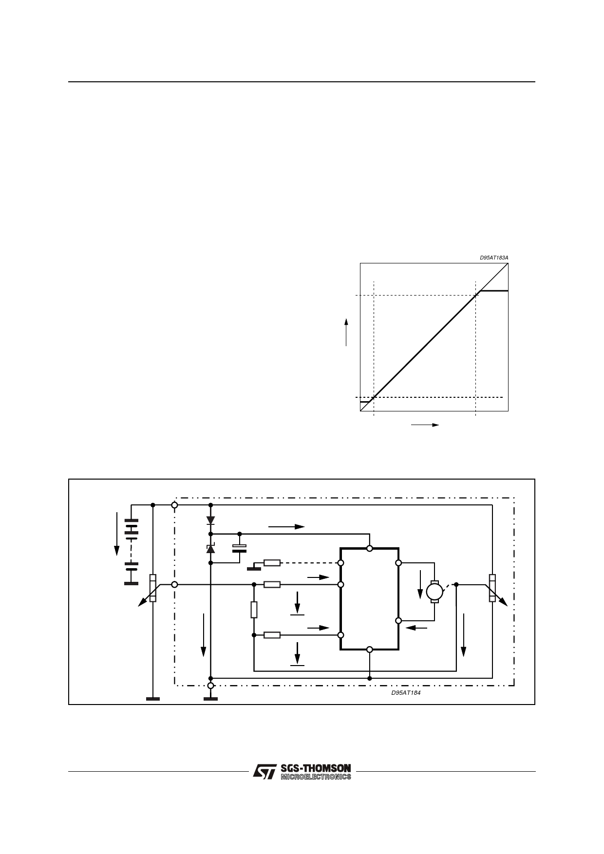
Figure 2: Control to feedback transfer characteristic
for tracking regulation (VF = VC within
the nominal VINC operating range):
VBAT
D95AT183A
VS -2V
VF
1.5V
0
1.5V
VC
VS -2V VBAT
Figure 3: Recommended Application Circuit Diagram with L9907N for tracking regulation
(VF = VC for 1.5V < VC < VS -2V):
MODULE
VBAT
D1
IQ
D2
CS RPR
VS
PR
OUT C
RC
VC
RINC
IINC
RF
RCF
VINC
INC L9907N VM M
OUT F
RINF
IINF
INF
IM
VF
VINF
GND
D95AT184
Note:
Recommended value of RINC, RINF (equivalent input resistance to INC and INF) is 5KΩ to 10KΩ. Resistor RCF should assure that the differential
input voltage |VINC - VINF| remains within the NEUTRAL ZONE, when the control signal wire become broken. When this condition is fulfiled the
motor will not change its previous position.
4/8
Share Link: 