L78M05CS Ver la hoja de datos (PDF) - STMicroelectronics
Número de pieza
componentes Descripción
Fabricante
L78M05CS Datasheet PDF : 19 Pages
| |||
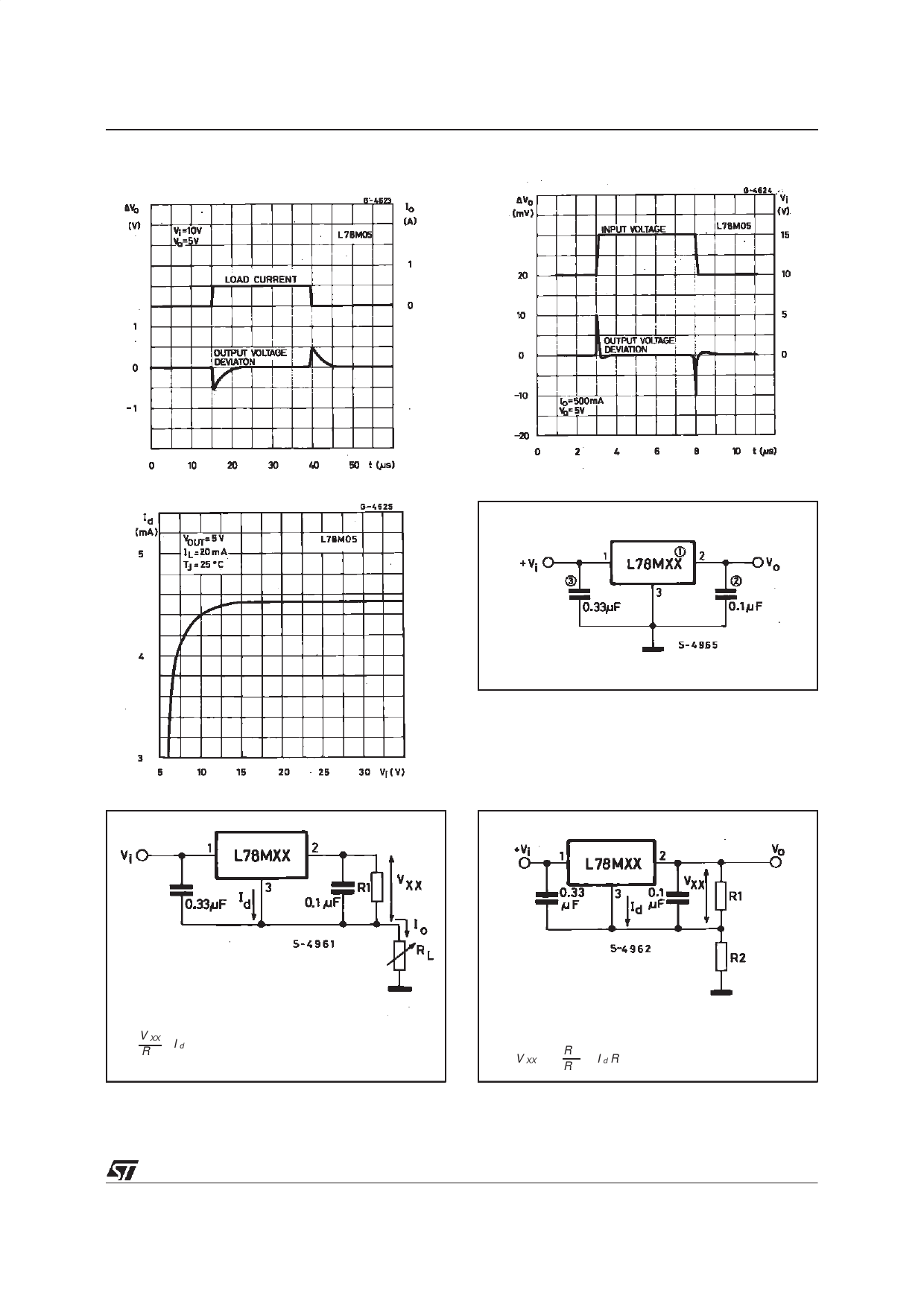
Figure 10 : Load Transient Response.
L78M00
Figure 11 : Line Transient Response.
Figure 12 : Quiescent Current vs. Input Voltage.
Figure 13 : Fixed Output Regulator.
NOTE:
1. To specify an output voltage, substitute voltage value for ”XX”.
2. Although no output capacitor is need for stability, it does
improve transient response.
3. Required if cregulator is locate an appreciable distance from
power supply filter.
IO
=
V XX
R1
+
I
d
IR1 ≥ 5 Id
VO
=
V
XX
(1
+
R
R
2)
1
+
I
d
R
2
11/19
Share Link: 