L6563 Ver la hoja de datos (PDF) - STMicroelectronics
Número de pieza
componentes Descripción
Fabricante
L6563 Datasheet PDF : 37 Pages
| |||
L6563 - L6563A
4
Electrical characteristics
Electrical characteristics
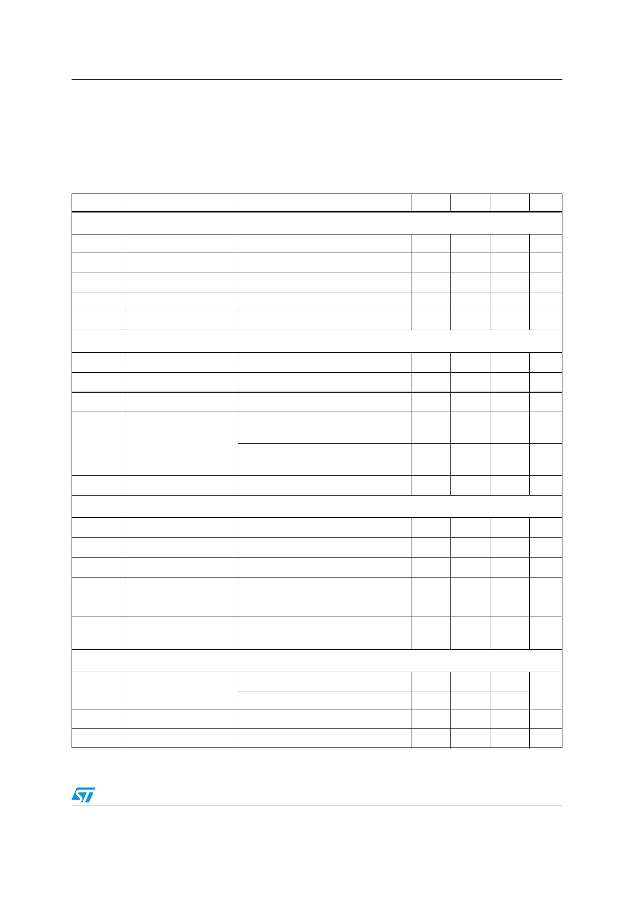
Table 4. Electrical characteristics
( -25°C < TJ < +125°C, VCC = 12V, Co = 1nF between pin GD and GND, CFF =1µF between pin VFF
and GND; unless otherwise specified)
Symbol
Parameter
Test condition
Min Typ Max Unit
Supply voltage
Vcc
VccOn
VccOff
Hys
VZ
Operating range
Turn-on threshold
Turn-off threshold
Hysteresis
Zener Voltage
After turn-on
(1)
(1)
Icc = 20 mA
10.3
22
V
11
12
13
V
8.7
9.5 10.3 V
2.3
2.7
V
22
25
28
V
Supply current
Istart-up
Iq
ICC
Iqdis
Iq
Start-up current
Before turn-on, Vcc=10V
Quiescent current
After turn-on
Operating supply current @ 70kHz
Idle state quiescent
Current
Quiescent current
Latched by PFC_OK>Vthl or
Vcs>VCSdis
Disabled by PFC_OK<Vth or
RUN<VDIS
During static/dynamic OVP
50
90
µA
3
5
mA
3.8
5.5 mA
180 250 µA
1.5
2.2 mA
2
3
mA
Multiplier input
IMULT
VMULT
VCLAMP
Input bias current
Linear operation range
Internal clamp level
VMULT = 0 to 3 V
IMULT = 1 mA
-0.2
-1
µA
0 to 3
V
9
9.5
V
-----∆----V----c--s------
∆V M U L T
Output max. slope
VMULT=0 to 0.5V, VFF=0.8V
VCOMP = Upper clamp
2.2 2.34
V/V
KM
Gain (3)
VMULT = 1 V, VCOMP= 4 V,
VVFF = VMULT
0.375 0.45 0.525 V
Error amplifier
VINV
IINV
Voltage feedback input
threshold
Line regulation
Input bias current
Tj = 25 °C
10.3 V < Vcc < 22 V (2)
Vcc = 10.3 V to 22V
TBO open, VINV = 0 to 4 V
2.465 2.5 2.535
V
2.44
2.56
2
5
mV
-0.2
-1
µA
7/37
Share Link: 