L6562AT Ver la hoja de datos (PDF) - STMicroelectronics
Número de pieza
componentes Descripción
Fabricante
L6562AT Datasheet PDF : 25 Pages
| |||
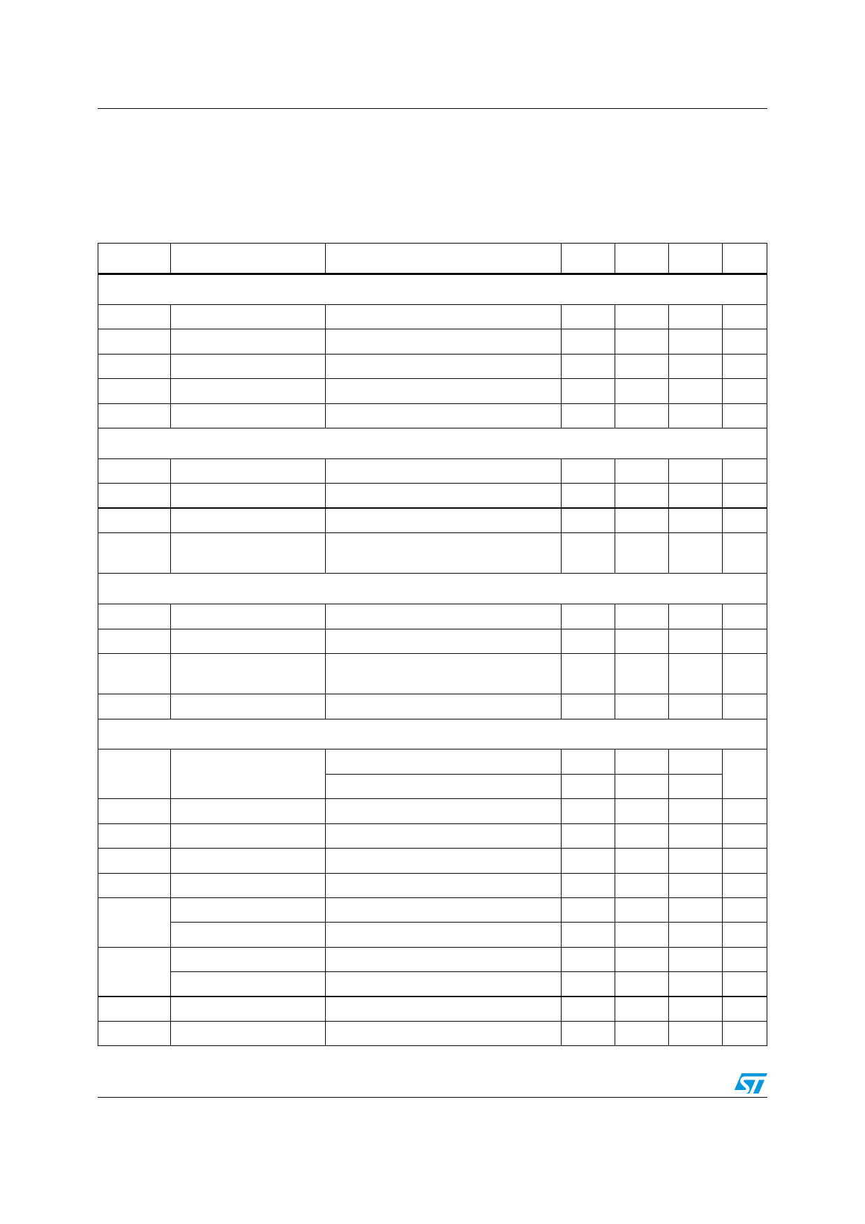
Electrical characteristics
5
Electrical characteristics
L6562AT
-40 °C < TJ < +125 °C, VCC = 12 V, CO = 1 nF; unless otherwise specified
Table 5. Electrical characteristics
Symbol
Parameter
Test condition
Min Typ
Supply voltage
VCC
VccOn
VccOff
Hys
Operating range
Turn-on threshold
Turn-off threshold
Hysteresis
After turn-on
(1)
(1)
VZ
Zener voltage
Supply current
ICC = 20 mA
Istart-up
Iq
ICC
Iq
Start-up current
Quiescent current
Before turn-on, VCC = 11 V
After turn-on
Operating supply current @ 70 kHz
Quiescent current
During OVP (either static or dynamic)
or VINV ≤ 150 mV
Multiplier input
IMULT
VMULT
-----Δ----V----c--s------
ΔV M U L T
K
Input bias current
Linear operation range
Output max. slope
Gain (2)
Error amplifier
VMULT = 0 to 4 V
VMULT = 0 to 1 V,
VCOMP = Upper clamp
VMULT = 1 V, VCOMP = 4 V,
VINV
IINV
Gv
GB
ICOMP
VCOMP
VINVdis
VINVen
Voltage feedback input
threshold
Line regulation
Input bias current
Voltage gain
TJ = 25 °C
10.5 V < VCC < 22.5 V (1)
VCC = 10.5 V to 22.5 V
VINV = 0 to 3 V
Open loop
Gain-bandwidth product
Source current
Sink current
Upper clamp voltage
Lower clamp voltage
Disable threshold
VCOMP = 4 V, VINV = 2.4 V
VCOMP = 4 V, VINV = 2.6 V
ISOURCE = 0.5 mA
ISINK = 0.5 mA (1)
Restart threshold
10.5
11.7
9.5
2.2
22.5
0 to 3
1
0.32
2.475
2.44
60
-2
2.5
5.1
2.1
150
380
12.5
10
25
30
2.5
3.5
1.7
1.1
0.38
2.5
2
80
1
-3.5
4.5
5.7
2.25
200
450
Max Unit
22.5 V
13.3 V
10.5 V
2.8
V
28
V
60
µA
3.9 mA
5.5 mA
2.2 mA
-1
µA
V
V/V
0.47 V
2.525
2.545
5
-1
-5
6
2.4
250
520
V
mV
µA
dB
MHz
mA
mA
V
V
mV
mV
6/25
Share Link: 