AD608 Ver la hoja de datos (PDF) - Analog Devices
Número de pieza
componentes Descripción
Fabricante
AD608 Datasheet PDF : 16 Pages
| |||
AD608
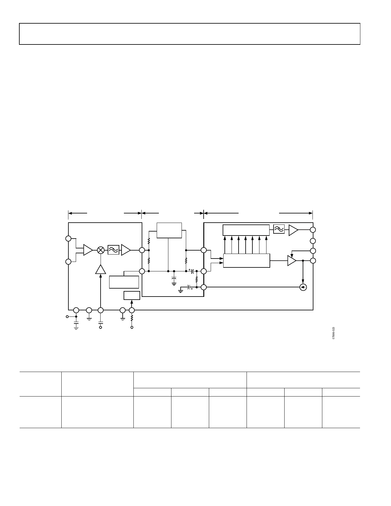
IF FILTER TERMINATIONS
The AD608 was designed to drive a parallel-terminated 10.7 MHz
band-pass filter (BPF) with a 330 Ω impedance. With a 330 Ω
parallel-terminated filter, Pin MXOP sees a 165 Ω termination,
and the gain is nominally 24 dB. Other filter impedances and
gains can be accommodated by either accepting an increase or
decrease in gain in proportion to the filter impedance or by
keeping the impedance seen by MXOP at a nominal 165 Ω (by
using resistive dividers or matching networks). Figure 23 shows a
simple resistive voltage divider for matching an assortment of
filter impedances, and Table 6 lists component values.
THE LOGARITHMIC IF AMPLIFIER
The logarithmic IF amplifier consists of five amplifier stages
of 16 dB gain each, plus a final limiter. The IF bandwidth is
30 MHz (−1 dB), and the limiting gain is 110 dB. The phase
skew is ±3° from −75 dBm to +5 dBm (approximately 111 μV p-p
to 1.1 V p-p). The limiter output impedance is 200 Ω, and the
limiter output drive is ± 200 mV (400 mV p-p) into a 5 kΩ load.
In the absence of an input signal, the limiter output limits noise
fluctuations, producing an output that continues to swing
400 mV p-p, but with random zero crossings.
OFFSET FEEDBACK LOOP
Because the logarithmic amplifier is dc-coupled and has more
than 110 dB of gain from the input to the limiter output, a dc
offset at its input of even a few microvolts causes the output to
saturate. Therefore, the AD608 uses a low frequency feedback
loop to null the input offset. Referring to Figure 23, the loop
consists of a current source driven by the limiter, which sends
50 μA current pulses to Pin FDBK. The pulses are low-pass filtered
by a π-network consisting of C1, R4, and C5. The smoothed dc
voltage that results is subtracted from the input to the IF amplifier
at Pin IFLO. Because this is a high gain amplifier with a feedback
loop, care should be taken in layout and component values to
prevent oscillation. Recommended values for the common IFs
of 450 kHz, 455 kHz, 6.5 MHz, and 10.7 MHz are listed in Table 6.
24dB MIXER GAIN
12dB NOMINAL
INSERTION LOSS
(ASSUMES 6dB IN FILTER)
110dB LIMITER GAIN
90dB RSSI
RFHI 5
RFLO 6
MIXER
LO
PREAMP
MXOP
7
BPF
DRIVER
VMID
8
MIDSUPPLY
IF BIAS
BIAS
BAND-PASS
FILTER
R2
R1
R3
C5
+
100nF
R4
C1
IFHI
9
10
IFLO
13
FDBK
VPS1 COM1
1
2
5V
C1
1µF
LOHI COM2 PRUP
3
4 16
C2
100pF
47kΩ
7 FULL-WAVE
RECTIFIER CELLS
2MHz
LPF
5-STAGE IF AMPLIFIER
(16dB PER STAGE)
FINAL
LIMITER
11 RSSI
12 COM3
14 VPS2
15 LMOP
AD608
±50µA
LO INPUT
–16dBm
CMOS LOGIC
INPUT
Figure 23. Applications Diagram for Common IFs and Filter Impedances
Table 6. AD608 Filter Termination and Offset-Null Feedback Loop Resistor and Capacitor Values for Common IFs
IF
450 kHz2
455 kHz
6.5 MHz
10.7 MHz
Filter Impedance
1500 Ω
1500 Ω
1000 Ω
330 Ω
Filter Termination Resistor
Values1 for 24 dB of Mixer Gain
R1
R2
R3
174 Ω
1330 Ω
1500 Ω
174 Ω
1330 Ω
1500 Ω
178 Ω
825 Ω
1000 Ω
330 Ω
0Ω
330 Ω
R4
1000 Ω
1000 Ω
100 Ω
100 Ω
Offset-Null
Feedback Loop Values
C1
C5
200 nF
100 nF
200 nF
100 nF
18 nF
10 nF
18 nF
10 nF
1 Resistor values were calculated so that R1 + R2 = ZFILTER and R1||(R2 + ZFILTER) = 165 Ω.
2 Operation at IFs of 450 kHz and 455 kHz requires use of an external low-pass filter with at least one pole at a cutoff frequency of 90 kHz (a decade below the ripple at 900 kHz).
Rev. C | Page 10 of 16
Share Link: 