KA3842 Ver la hoja de datos (PDF) - Fairchild Semiconductor
Número de pieza
componentes Descripción
Fabricante
KA3842 Datasheet PDF : 12 Pages
| |||
KA3842B/KA3843B/KA3844B/KA3845B
Electrical Characteristics (Continued)
(VCC=15V, RT=10KΩ, CT=3.3nF, TA= 0°C to +70°C unless otherwise specified)
Parameter
PWM SECTION
Max. Duty Cycle
Min. Duty Cycle
TOTAL STANDBY CURRENT
Start-Up Current
Operating Supply Current
Zener Voltage
Symbol
D(max)
D
D(MIN)
IST
ICC(OPR)
VZ
Conditions
KA3842B/KA3843B
KA3844B/KA3845B
-
-
V3=V2=ON
ICC = 25mA
Adjust VCC above the start threshould before setting at 15V
Note:
1. Parameter measured at trip point of latch
2. Gain defined as:
A = ∆∆-----VV----13-
,0 ≤ V3 ≤ 0.8V
3.These parameters, although guaranteed, are not 100 tested in production.
Min. Typ. Max. Unit
95 97 100 %
47 48 50 %
-
-
0
%
- 0.45 1 mA
-
14 17 mA
30
38
-
V
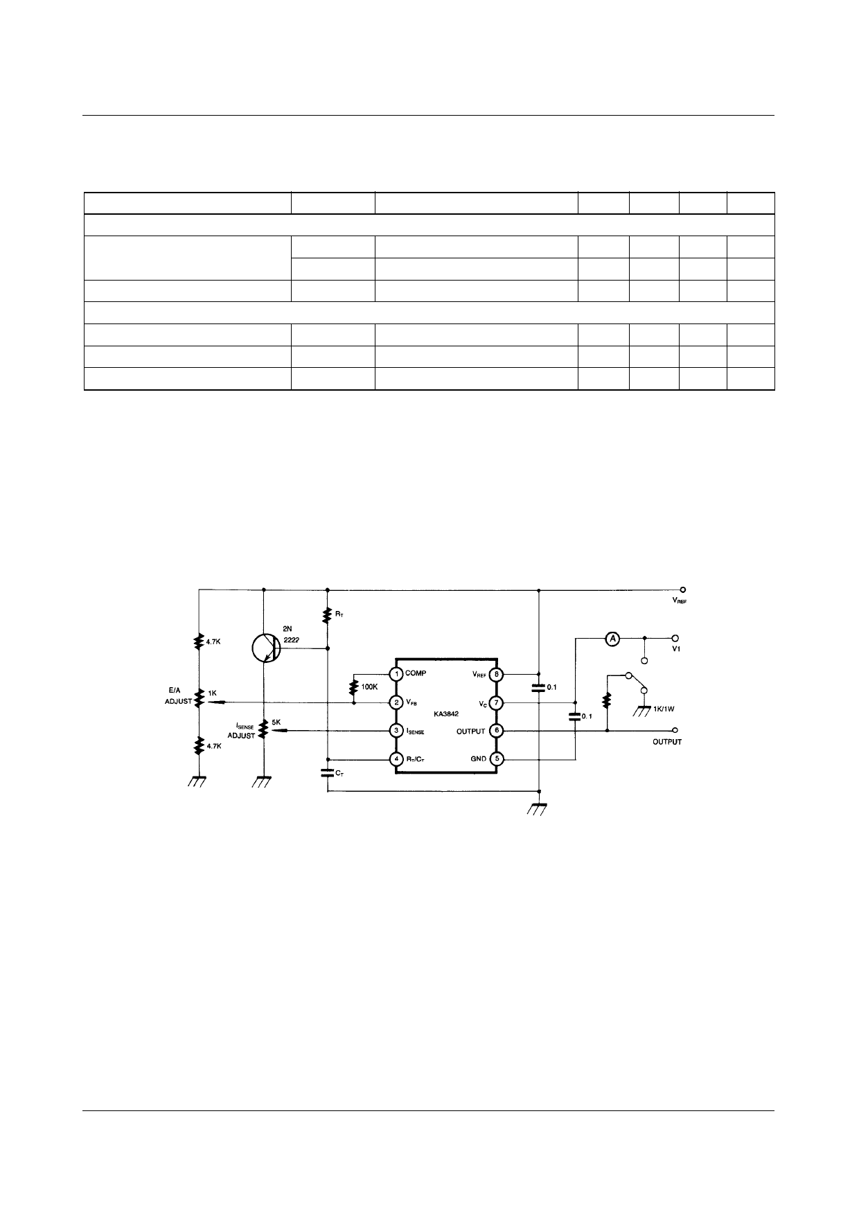
Figure 1. Open Loop Test Circuit
High peak currents associated with capacitive loads necessitate careful grounding techniques Timing and bypass capacitors
should be connected close to pin 5 in a single point ground. The transistor and 5KΩ potentiometer are used to sample the
oscillator waveform and apply an adjustable ramp to pin 3.
4
Share Link: 