IXGR32N170AH1 Ver la hoja de datos (PDF) - IXYS CORPORATION
Número de pieza
componentes Descripción
Fabricante
IXGR32N170AH1 Datasheet PDF : 2 Pages
| |||
IXGR 32N170AH1
Symbol
gfs
Cies
Coes
Cres
Qg
Qge
Qgc
td(on)
tri
td(off)
tfi
Eoff
Test Conditions
Characteristic Values
(TJ = 25°C unless otherwise specified)
min. typ. max.
IC = IC25; VCE = 10 V
Note 2
VCE = 25 V, VGE = 0 V, f = 1 MHz
25 33
S
3700
pF
180
pF
44
pF
IC = IC90, VGE = 15 V, VCE = 0.5 VCES
Inductive load, TJ = 25°C
IC = IC90, VGE = 15 V
RG = 2.7 Ω, VCE = 0.8 VCES
Note 3
155
nC
30
nC
51
nC
46
ns
57
ns
270 500 ns
50 100 ns
1.5 3.0 mJ
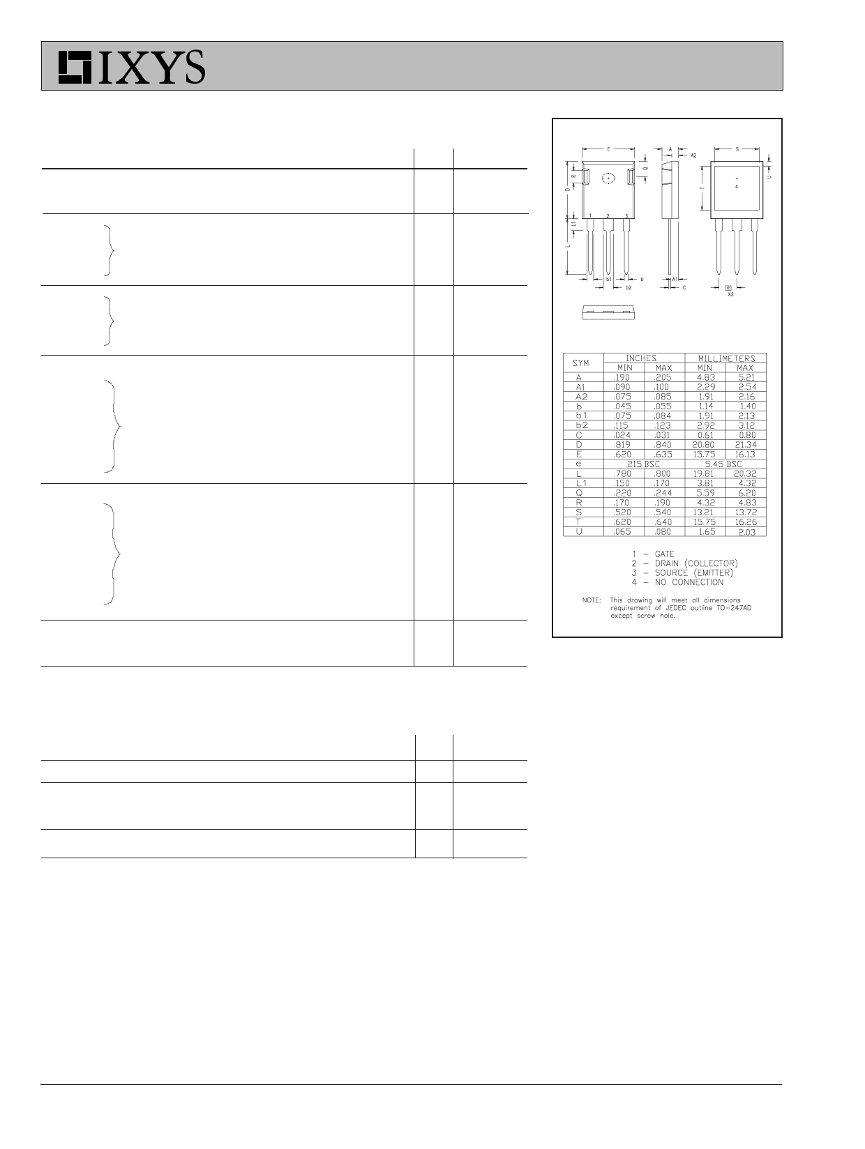
ISOPLUS247 Outline
td(on)
tri
Eon
td(off)
tfi
Eoff
RthJC
RthCK
Inductive load, TJ = 125°C
IC = IC90, VGE = 15 V
RG = 2.7 Ω, VCE = 0.8 VCES
Note 3
48
ns
42
ns
2.5
mJ
300
ns
70
ns
2.4
mJ
0.65 K/W
0.15
K/W
Reverse Diode (FRED)
Symbol
Test Conditions
Characteristic Values
(TJ = 25°C, unless otherwise specified)
min. typ. max.
VF
IRM
trr
RthJC
IF = 20A, VGE = 0 V, Note 2
IF = 50A, VGE = 0 V, -diF/dt = 800 A/µs
VR = 600 V
2.7
V
50
A
150
ns
1.5 K/W
See IXGX32N170AH1 for
charcteristic curves
Notes: 1.
2.
3.
4.
Device must be heatsunk for high temperature leakage current
measurements to avoid thermal runaway.
Pulse test, t ≤ 300 µs, duty cycle ≤ 2 %
Switching times may increase for VCE (Clamp) > 0.8 • VCES, higher TJ or
iSnecereDasHe6d0-R1G8.A and IXGH32N170A datasheets for additional
characteristics
IXYS reserves the right to change limits, test conditions, and dimensions.
IXYS MOSFETs and IGBTs are covered by
one or moreof the following U.S. patents:
4,835,592
4,850,072
4,881,106
4,931,844
5,017,508
5,034,796
5,049,961
5,063,307
5,187,117
5,237,481
5,381,025
5,486,715
6,162,665
6,259,123 B1
6,306,728 B1
6,404,065 B1
6,534,343
6,583,505
6,683,344
6,710,405B2
6,710,463
6,727,585
6,759,692
Share Link: 