IRK.71 Ver la hoja de datos (PDF) - International Rectifier
Número de pieza
componentes Descripción
Fabricante
IRK.71 Datasheet PDF : 10 Pages
| |||
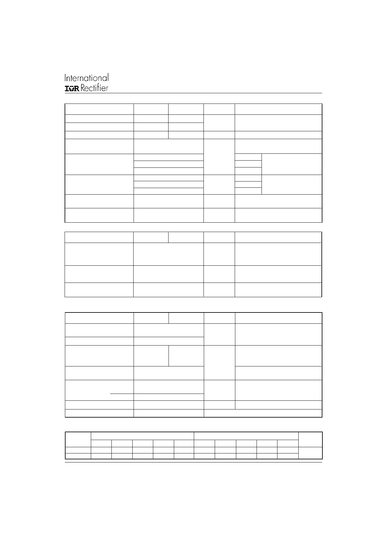
Triggering
IRK.71, .91 Series
Bulletin I27132 rev. H 10/02
Parameters
PGM Max. peak gate power
PG(AV) Max. average gate power
IGM
-VGM
Max. peak gate current
Max. peak negative
gate voltage
VGT Max. gate voltage
required to trigger
IGT Max. gate current
required to trigger
VGD Max. gate voltage
that will not trigger
IGD Max. gate current
that will not trigger
Blocking
IRK.71
12
3.0
3.0
IRK.91
12
3.0
3.0
10
4.0
2.5
1.7
270
150
80
0.25
6
Units Conditions
W
A
V
TJ = - 40°C
Anode supply = 6V
TJ = 25°C
resistive load
TJ = 125°C
TJ = - 40°C
Anode supply = 6V
mA
TJ = 25°C
resistive load
TJ = 125°C
V
TJ = 125oC,
rated VDRM applied
mA
TJ = 125oC,
rated VDRM applied
Parameters
IRK.71
IRK.91
Units
IRRM Max. peak reverse and
IDRM off-state leakage current
15
mA
at VRRM, VDRM
2500 (1 min)
VINS RMS isolation voltage
3500 (1 sec)
V
dv/dt Max. critical rate of rise
500
of off-state voltage (5)
V/µs
(5) Available with dv/dt = 1000V/µs, to complete code add S90 i.e. IRKT91/16AS90.
Thermal and Mechanical Specifications
Conditions
TJ = 125 oC, gate open circuit
50 Hz, circuit to base, all terminals
shorted
TJ = 125oC, linear to 0.67 VDRM,
gate open circuit
Parameters
IRK.71
IRK.91
Units
Conditions
TJ Junction operating
temperature range
Tstg
RthJC
Storage temp. range
Max. internal thermal
resistance, junction
to case
RthCS Typical thermal resistance
case to heatsink
T Mounting torque ± 10%
to heatsink
busbar
wt Approximate weight
- 40 to 125
- 40 to 125
0.165
0.135
0.1
5
3
110 (4)
°C
K/W
Nm
gr (oz)
Per module, DC operation
Mounting surface flat, smooth and greased
A mounting compound is recommended
and the torque should be rechecked after
a period of 3 hours to allow for the
spread of the compound
Case style
TO-240AA
JEDEC
∆R Conduction (per Junction)
(The following table shows the increment of thermal resistance RthJC when devices operate at different conduction angles than DC)
Devices
180o
Sine half wave conduction
120o
90o
60o
30o
Rect. wave conduction
180o
120o
90o
60o
30o
Units
IRK.71
0.06
0.07
0.09
0.12
0.18
0.04
0.08
0.10
0.13
0.18
°C/W
IRK.91
0.04
0.05
0.06
0.08
0.12
0.03
0.05
0.06
0.08
0.12
www.irf.com
3
Share Link: 