IRK.91 Ver la hoja de datos (PDF) - International Rectifier
Número de pieza
componentes Descripción
Fabricante
IRK.91 Datasheet PDF : 10 Pages
| |||
IRK.71, .91 Series
Bulletin I27132 rev. H 10/02
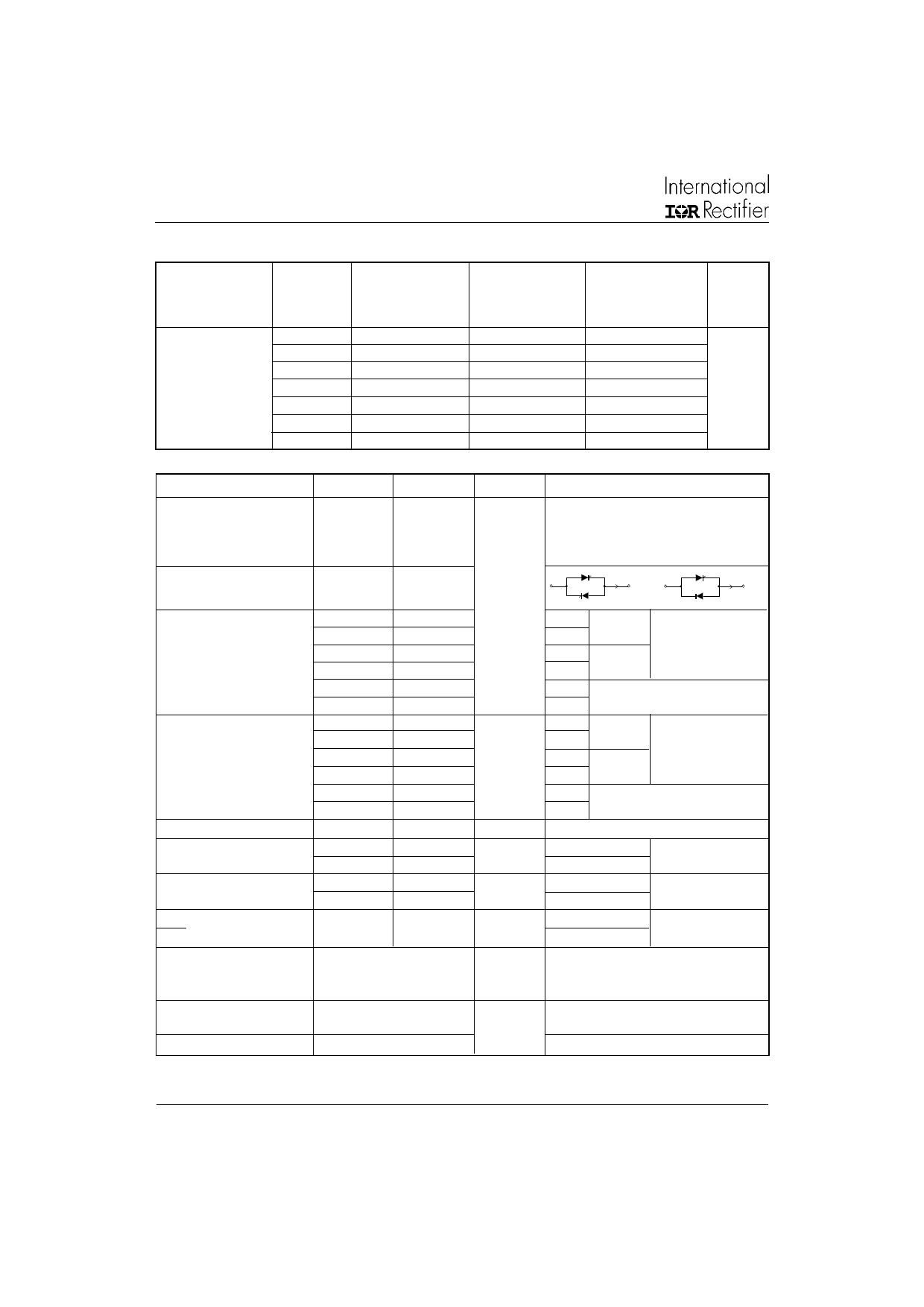
ELECTRICAL SPECIFICATIONS
Voltage Ratings
Type number
Voltage
Code
-
04
VRRM , maximum
repetitive
peak reverse voltage
V
400
VRSM , maximum VDRM , max. repetitive
non-repetitive peak off-state voltage,
peak reverse voltage gate open circuit
V
V
500
400
06
600
700
600
08
800
900
800
IRK.71/ .91
10
1000
1100
1000
12
1200
1300
1200
14
1400
1500
1400
16
1600
1700
1600
IRRM
IDRM
125°C
mA
15
On-state Conduction
Parameters
IRK.71
IRK.91
Units Conditions
IT(AV) Max. average on-state
current (Thyristors)
75
95
IF(AV) Max. average forward
current (Diodes)
180o conduction, half sine wave,
TC = 85oC
IO(RMS)
Max. continuous RMS
on-state current.
As AC switch
ITSM Max. peak, one cycle
or non-repetitive on-state
IFSM or forward current
I2 t Max. I2t for fusing
I2√t Max. I2√t for fusing (1)
165
1665
1740
1400
1470
1850
1940
13.86
12.56
9.80
8.96
17.11
15.60
138.6
210
1785
1870
1500
1570
2000
2100
15.91
14.52
11.25
10.27
20.00
18.30
159.1
A
KA2s
KA2√s
or
I(RMS)
I(RMS)
t=10ms No voltage
t=8.3ms reapplied
t=10ms 100% VRRM
t=8.3ms reapplied
Sinusoidal
half wave,
Initial TJ = TJ max.
t=10ms TJ = 25oC,
t=8.3ms no voltage reapplied
t=10ms No voltage
t=8.3ms reapplied
t=10ms 100% VRRM
t=8.3ms reapplied
Initial TJ = TJ max.
t=10ms TJ = 25oC,
t= 8.3ms no voltage reapplied
t=0.1 to 10ms, no voltage reapplied
VT(TO) Max. value of threshold
voltage (2)
0.82
0.85
0.80
0.85
Low level (3)
V
High level (4)
TJ = TJ max
rt
Max. value of on-state
3.00
slope resistance (2)
2.90
2.40
2.25
Low level
mΩ
High level (4)
(3)
TJ = TJ max
VTM Max. peak on-state or
VFM forward voltage
di/dt Max. non-repetitive rate
of rise of turned on
current
IH
Max. holding current
1.59
1.58
150
200
V
A/µs
mA
ITM = π x IT(AV)
IFM = π x IF(AV)
TJ = 25°C
TJ = 25oC, from 0.67 VDRM,
ITM =π x , IT(AV) Ig = 500mA,
tr < 0.5 µs, tp > 6 µs
TJ = 25oC, anode supply = 6V,
resistive load, gate open circuit
IL
Max. latching current
400
TJ = 25oC, anode supply = 6V, resistive load
(1) I2t for time tx = I2√t x √tx
(4) I > π x IAV
(2) Average power = VT(TO) x IT(AV) + rt x (IT(RMS))2
(3) 16.7% x π x IAV < I < π x IAV
2
www.irf.com
Share Link: 