IS25F011A Ver la hoja de datos (PDF) - Integrated Silicon Solution
Número de pieza
componentes Descripción
Fabricante
IS25F011A
Integrated Silicon Solution

IS25F011A Datasheet PDF : 23 Pages
| |||
IS25F011A
IS25F021A
IS25F041A
Serial Flash Memory Array
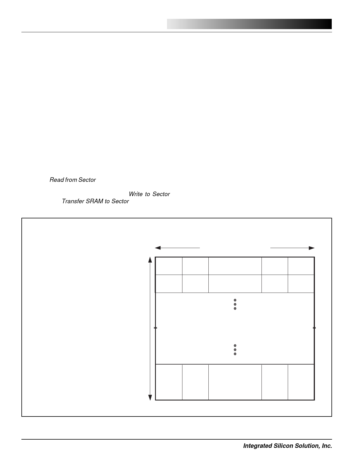
The IS25F011A, IS25F021A, and IS25F041A Serial Flash
memory arrays are organized as 512, 1024, and 2048
sectors of 264-bytes (2,112 bits) each, as shown in Figure
4. Grouping sectors as pairs offer a convenient format for
applications that store and transfer data in a DOS compat-
ible sector size of 512-bytes. The additional 16-bytes per
sector pair can be used for sector management such as
header, checksum, CRC, or other related application
requirements.
The Serial Flash memory of the IS25F011A, IS25F021A,
and IS25F041A is byte-addressable. That is, each sector
is individually addressable and each byte within a sector
is individually addressable. This allows a single byte, or
specified sequence of bytes, to be read without having to
clock an entire 264-byte sector out of the device. Data can
be read directly from a sector in the Flash memory array
by using a Read from Sector command from the SPI bus.
Data can be written to a sector in the Flash memory array
by means of the Serial SRAM using a Write to Sector
command or a Transfer SRAM to Sector command.
ISSI ®
After a sector has been written, the memory array will
become busy while it is programming the specified non-
volatile memory cells of that sector. This busy time will not
exceed tWP (~5 ms for 5V devices), during which time the
Flash array is unavailable for read or write access. The
device can be tested to determine the array’s availabil-
ity using the Ready/Busy status that is available during
most read commands, via the status register, or on the
Ready/Busy pin. Note that the SRAM is always available,
even when the memory array is busy. See the Serial
SRAM section for more details.
The IS25F011A, IS25F021A, and IS25F041A do not
require pre-erase. Instead, the device incorporates an
auto-erase-before-write feature that automatically erases
the addressed sector at the beginning of the write opera-
tion. This allows for fast and consistent programming
times. It also simplifies firmware support by eliminating
the need for a separate pre-erase algorithm and the
complex management of disproportional erase and write
block sizes commonly found in other devices.
Sector Address:
25F011
S[8:0]
25F021
S[9:0]
25F041
S[10:0]
Sector 511
1FFH
Sector 1023 Sector 2047
3FFH
7FFH
Sector 510
1FEH
Sector 1022 Sector 2046
3FEH
7FEH
Byte 0
000H
Byte 0
000H
Byte Address: B[8:0]
Byte1
001H
Byte1
001H
Byte 2-261
002H-105H
Byte 2-261
002H-105H
Byte 262 Byte 263
106H
107H
Byte 262 Byte 263
106H
107H
Sector 2-509 Sector 2-1021 Sector 2-2045
002H-1FDH 002H-3FDH 002H-7FDH
1M-bit, 2M-bit, or 4M-bit Serial Flash Memory Array
512, 1024, and 2048 Byte-Addressable Sectors
of 264-Bytes each
Sector 1
001H
Sector 0
000H
Sector 1
001H
Sector 0
000H
Sector 1
001H
Sector 0
000H
Byte 0
000H
Byte 0
000H
Byte 1
001H
Byte 1
001H
Byte 2-261
002H-105H
Byte 2-261
002H-105H
Byte 262 Byte 263
106H
107H
Byte 262 Byte 263
106H
107H
Figure 4. IS25F011A, IS25F021A, and IS25F041A Serial Flash Memory Array
4
Integrated Silicon Solution, Inc.
PRELIMINARY SF001-1A
06/24/98
Share Link: