IS25F011A Ver la hoja de datos (PDF) - Integrated Silicon Solution
Número de pieza
componentes Descripción
Fabricante
IS25F011A
Integrated Silicon Solution

IS25F011A Datasheet PDF : 23 Pages
| |||
IS25F011A
IS25F021A
IS25F041A
ISSI ®
Read Device Information Sector
The Read Device Information command provides access
to a read-only sector that can be used to electronically
identify the ISSI Serial Flash device being interfaced to.
Information available includes: part number, density,
voltage, temperature range, package type, and any
special options. This can be extremely useful for sys-
tems that need to accommodate optional densities
1 (e.g., both 1M-bit or 4M-bit). In this case the firmware
can interrogate the Device Information Sector and de-
termine the density. The Device Information Sector also
includes a list of any restricted sectors that might exist
2 in the device. Contact ISSI for more detailed information
on the Device Information Sector format.
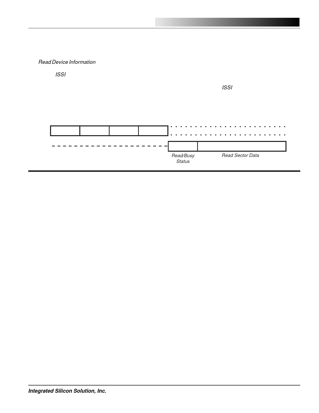
Read Device
Info. Sector
Byte
3
Command 16 Clocks Address* 16 Clocks
SI
15H
0000H
B[15:0]
0000H
4
SO
RB[15:0]
First Byte - Last Byte
*The byte address only uses bits [8:0]
Read/Busy
Read Sector Data
Status
5
Sector Format and Tag/Sync Bytes
The first byte of each sector is pre-programmed during
manufacturing with a tag/sync value of C9H. Although
this byte location of the sector can be changed, it is
recommended that it be maintained and incorporated
into the application’s sector formatting.
The tag/sync values serve two purposes. First, they
provide a sync-detect that can help verify if the command
sequence was clocked into the device properly. Sec-
ondly, they serve as a tag to identify a fully functional
(valid) sector. This is especially important if “restricted
sector” devices are ever to be used. Restricted sector
devices provide a more cost effective alternative to
standard devices with 100% valid sectors. Restricted
sector devices have a limited number of sectors that do
not meet manufacturing programming criteria over the
specified operating range. When such a sector is de-
tected, the first byte is tagged with a pattern other than
C9H. In addition to individual sector tagging, all restricted
sectors for a given device are listed in the Device Infor-
mation Sector. For more information see the Device
Information Sector Application Note SFAN-02.
High Data Integrity Applications
6
Data storage applications that use Flash memory or other
non-volatile media must take into consideration the possi-
bility of noise or other adverse system conditions that may
7 affect data integrity. For those applications that require
higher levels of data integrity it is a recommended practice
to use Error Correcting Code (ECC) techniques. The
IS-SFK-SPI Serial Flash Development Kit provides a
8 software routine for a 32-bit ECC that can detect up to two
bit errors and correct one. The ECC not only minimizes
problems caused by system noise but can also extend
Flash memory endurance. For those systems without the
9 processing power to handle ECC algorithms, a simple
“verification after write” is recommended. The "Compare
Sector to SRAM" command can be useful for implement-
ing this Write/Verify operation. The IS-SFK-SPI software
10 includes a simple Write/Verify routine that will compare
data written to a given sector and rewrite the sector if the
compare is not correct.
11
12
Integrated Silicon Solution, Inc.
19
PRELIMINARY SF001-1A
06/24/98
Share Link: