IR21571 Ver la hoja de datos (PDF) - International Rectifier
Número de pieza
componentes Descripción
Fabricante
IR21571 Datasheet PDF : 17 Pages
| |||
IR21571(S)
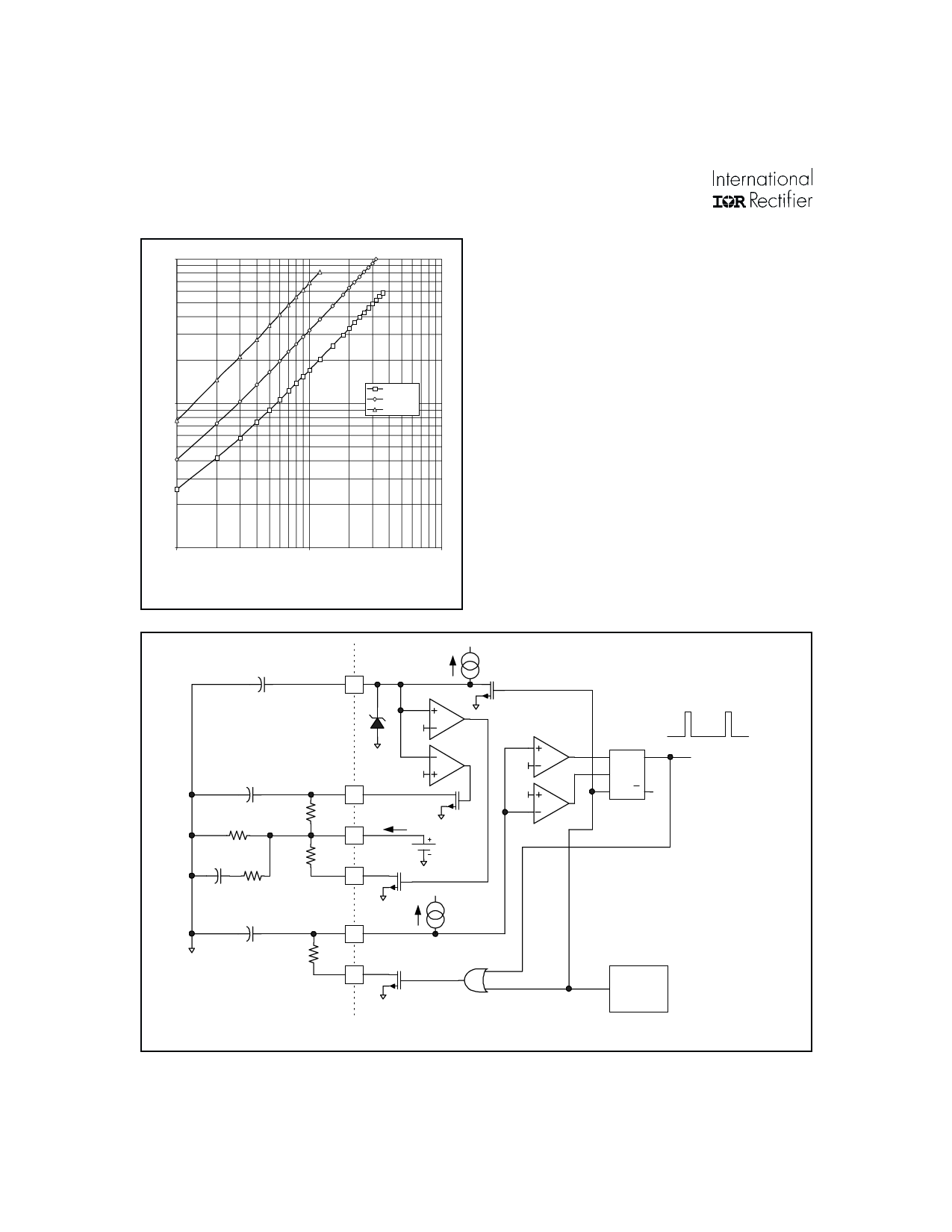
10
tDEAD
(usec)
1
CT = 220 pF
CT = 470 pF
CT = 1 nF
0.1
1
10
100
RDT (Kohms)
Figure 5: Deadtime versus RDT
During the Startup Mode, the operating frequency is
determined by the parallel combination of RPH,
RSTART, and RT, combined with the values of CSTART,
CT and RDT , as shown in Figure 6. This frequency is
normally chosen to ensure that the instantaneous
voltage across the lamp during the first few cycles of
operation does not exceed the strike potential of the
lamp. As the voltage across CSTART charges up to the
RT lead voltage, the output frequency exponentially
decays to the preheat frequency.
During the Preheat Mode, the operating frequency
is determined by the parallel combination of RPH and
RT, combined with the value of CT and RDT. This
frequency, along with the Preheat Time, is normally
chosen to ensure that adequate heating of the lamp
filaments occur. Typically, a 4.5:1 ratio of the hot
filament-to-cold filament resistance is desired for
maximum lamp life, as shown in Figure 7.
CPH
CPH
2
7.6V
1.0uA
5.1V
4.0V
RPH
4.0V
3
2.0V
CIGN
RPH
RT
RRUN
CSTART RSTART
RT
4
RUN
5
IRT
2.0V
SQ
R1
R2 Q
CT
ICT = IRT
6
CT
RDT
DT
7
UNDER-
VOLTAGE
DETECT
Figure 6: Oscillator section block diagram with external component connection
10
www.irf.com
Share Link: 