IMP560 Ver la hoja de datos (PDF) - IMP, Inc
Número de pieza
componentes Descripción
Fabricante
IMP560 Datasheet PDF : 8 Pages
| |||
IMP560
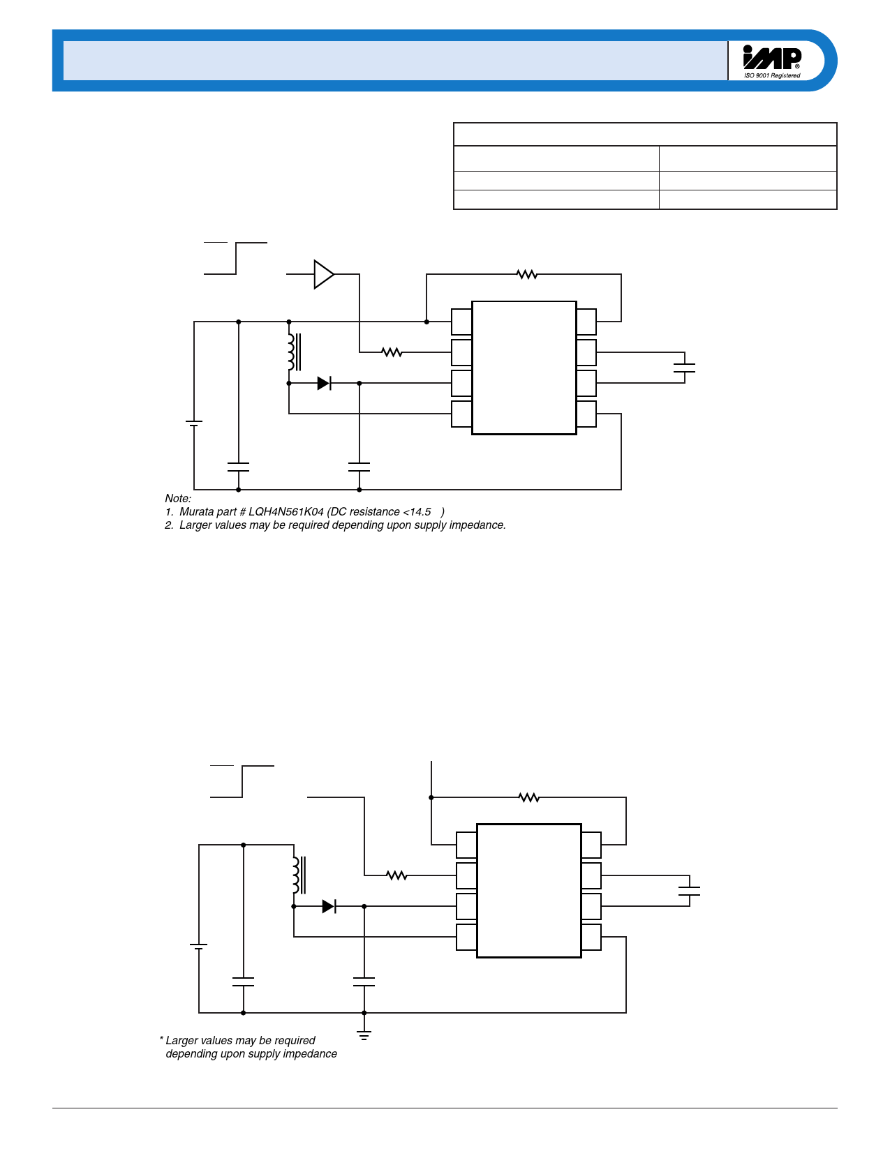
Enable/Disable Operation
Figure 3 shows the IMP560 can be enabled via a logic gate that con-
nects RSW to VDD, and disabled by connecting it to ground. RELmay
be connected either to VDD or to the gate.
Enable/Disable Table
RSW Connection
VDD
Ground
ON = VDD
CMOS
Gate
REL
OFF = 0V
IMP560 State
Enabled
Disabled
+
VIN –
RSW
L1
1N4148
0.1µF2
15V
0.1µF
100V
1 VDD
REL-OSC 8
2 RSW-OSC
VA 7
3 CS
VB 6
4 LX
GND 5
IMP560
Note:
1. Murata part # LQH4N561K04 (DC resistance <14.5 Ω)
2. Larger values may be required depending upon supply impedance.
Figure 3. Enable/Disable Operation
EL lamp
560_11.eps
Dual Supply Operation with 1.5V Battery
The IMP560 can also be operate from a single battery cell when a
regulated voltage higher than 2.0V is also available. The dual
supply configuration, shown in Figure 4, uses the regulated
voltage to operate the IMP560 while the energy for the high-
voltage boost circuit comes from the battery. The current to run
the internal logic is typically 420µA.
The circuit of Figure 4 can also be used with batteries that exceed
6.0V as long as VDD does not exceed 6.5V.
ON = VDD
OFF = 0V
Regulated Voltage
(2.0V to 6.5V)
REL
Battery +
Voltage
VIN –
RSW
L
1N4148
0.1µF*
CS
0.1µF
100V
1 VDD
REL-OSC 8
2 RSW-OSC
VA 7
3 CS
VB 6
4 LX
GND 5
IMP560
EL lamp
* Larger values may be required
depending upon supply impedance
Figure 4. Dual Supply Operation with High Battery Voltages
560_12.eps
6
408-432-9100/www.impweb.com
© 2000 IMP, Inc.
Share Link: 