IM2000S Ver la hoja de datos (PDF) - Unspecified
Número de pieza
componentes Descripción
Fabricante
IM2000S Datasheet PDF : 16 Pages
| |||
Section 3
Operation of the IM2000S
Section Overview
This section covers the operation of the various circuits contained within the IM2000S Microstepping Controller ASIC.
These are:
!
Protection Inputs
!
Microstep Select (MSEL) Inputs
!
Step/Direction Inputs
!
Chip Select (CSEL) Input
!
Full Step Output
!
Dual PWM
!
Power Control Outputs
!
Controling the Output Current
!
Chopping Oscillator
!
Reset Input
!
External Look-up Table
!
Buss/Standalone Mode
Protection Inputs
The IM2000S has four inputs which will disable the PWM and driver control outputs to protect against external faults.
These inputs include:
!
Over Temperature
!
Phase A and Phase B Short Circuit
!
Over Voltage
All four inputs are buffered using Schmitt triggered buffers and are internally AND’ed together. These inputs may be
used independently or tied together for wired OR’ed protection circuits. Unused inputs must be tied to a logic HIGH
state.
Upon detection of a fault condition the IM2000S will latch the condition and set the fault output pin to a logic HIGH
state. At this time the phase control outputs, phase enable outputs and PWM are disabled. The IM2000S must be reset by
either pulling the reset input LOW, or cycling power to clear the fault condition and re-enable the PWM and driver
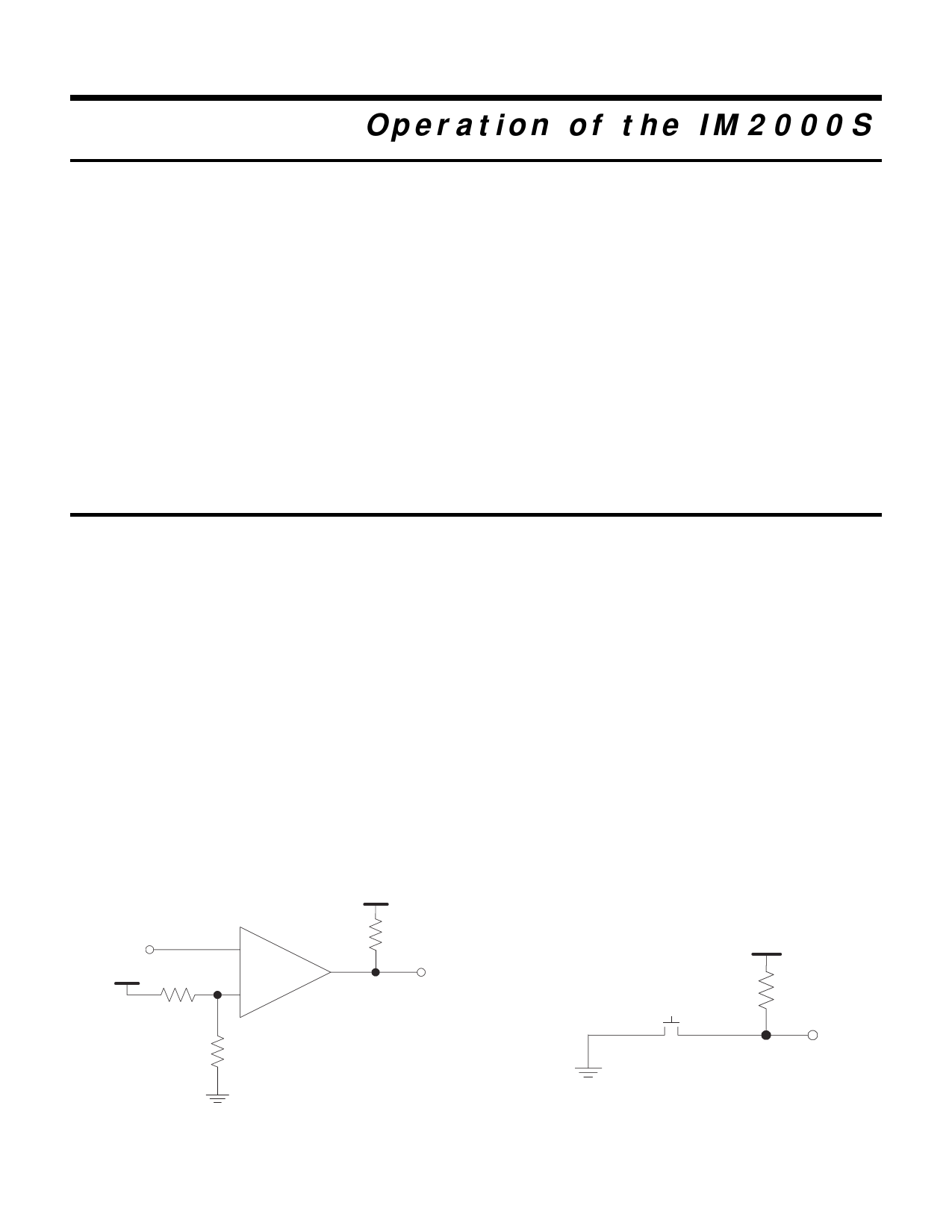
control outputs. Figures 3.1 and 3.2 illustrate possible application/interface of the overcurrent and over temperature
inputs.
+5V
Input from
Sense Resistor
_
10 kOhm
+5V
*
*Set Reference for
Maximum
Allowable Current
+
Comparator
Output to
OVCA/OVCB
Figure 3.1: Overcurrent Protection Example
+5V
10 kOhm
Thermostat
Output to
OVTMP
Figure 3.2: Thermal Protection Example
8
Share Link: 