IM2000S Ver la hoja de datos (PDF) - Unspecified
Número de pieza
componentes Descripción
Fabricante
IM2000S Datasheet PDF : 16 Pages
| |||
Chip Select (CSEL) Input
The CSEL input is used to select a number of functions
that are implemented using the MSEL0 and MSEL1 inputs.
If CSEL is low, or not connected, MSEL0 and MSEL1 will
function as microstep select lines as explained earlier.
If CSEL is high, MSEL0 and MSEL1 may be used to:
!
Reset the IM2000S.
!
Disable the PWM and driver control outputs.
!
Channel the Step Clock Input to COUT.
The relationship between the MSEL0 and MSEL1 inputs
and these special functions are illustrated in Table 3.2.
MSEL1
0
0
1
1
CSEL Settings
MSEL0
Function
0
SCLK to COUT
1
SCLK to COUT
0
Reset Controller
1
Disable Outputs
Table 3.2: Chip Select Settings
Full Step Output
This active high output indicates when the motor is electrically on a full step (the poles of the motor are aligned). This
occurs when either the sine or cosine outputs are at zero.
This signal may be used to greatly reduce the overhead needed to monitor position, decreasing the number of counts
needed to track position. By utilizing the full step output it is no longer necessary to keep track of the number of
microsteps between steps on moves until the last fractional step. With the full step output, it is possible to track position as
a combination of full steps plus the number of microsteps occuring after the last full step.
In the case of long moves at high resolutions this feature will reduce the position counter size and the overhead associ-
ated with updating/monitoring the position counter.
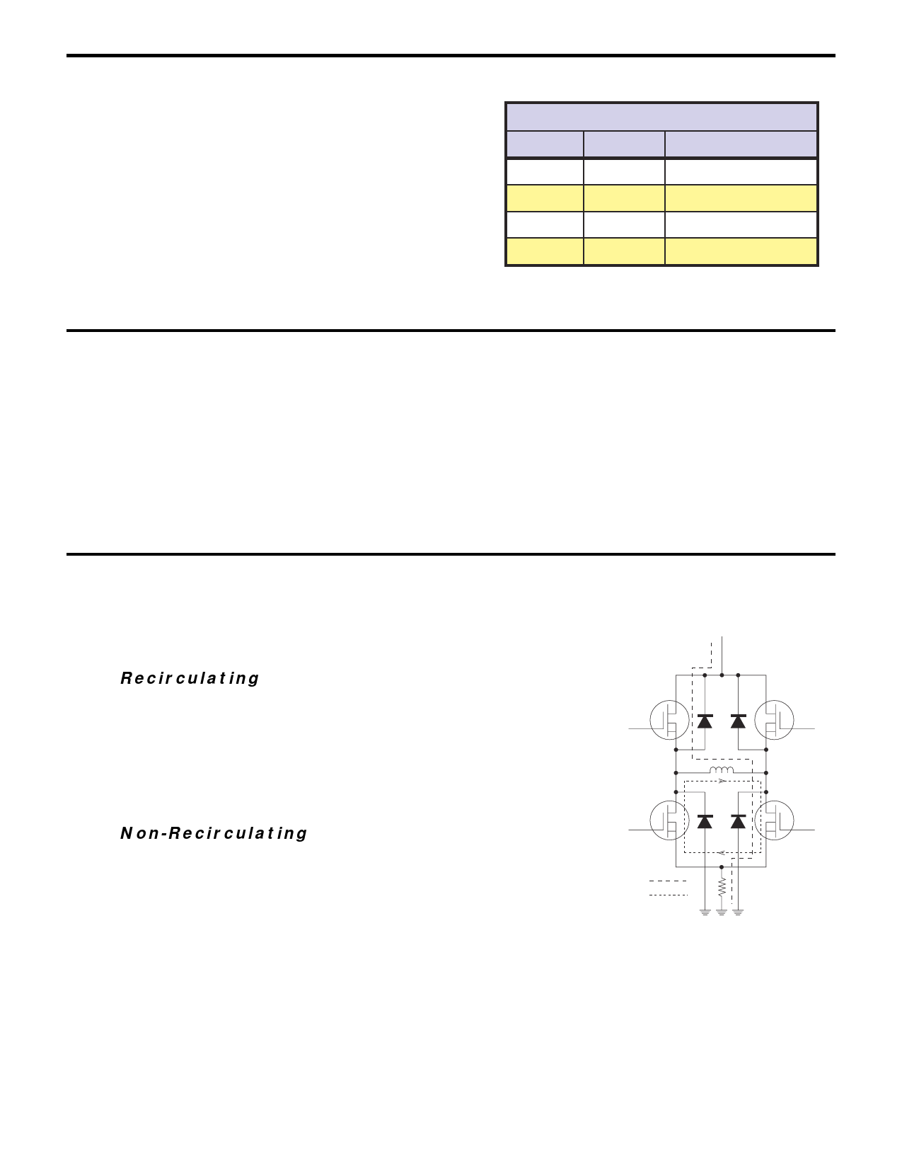
Dual PWM
The IM2000S contains a unique dual PWM circuit that efficiently and accurately regulates the current in the windings of a
two phase stepping motor. The internal PWM accomplishes this by using an alternating recirculating/non-recirculating
mode to control the current.
Recirculating
In a recirculating PWM, the current in the windings is contained within the
output bridge while the PWM is in its OFF state (after the set current is
reached). This method of controlling the current is efficient when using
low inductance motors, but lacks response because of its inability to
remove current from the windings on the downward cycle of the sine/
cosine wave (See Figure 3.3).
Non-Recirculating
In a non-recirculating PWM, the current flows up through the bridge and
back to the supply in the OFF phase of the cycle. This method of
controlling current allows for much better response but reduces efficiency
and increases current ripple, especially in lower inductance motors (See
Figure 3.4).
DRIVE CURRENT
RECIRCULATION
Figure 3.3: Recirculating PWM
The IM2000S PWM utilizes the best features of both by combining
recirculating and non-recirculating current control. On the rising edge of the sine/cosine waveform, the PWM will always be
in a recirculating mode. This mode allows the driver to run at peak efficiency while maintaining minimum current ripple even
with low inductance motors. On the downward cycle of the sine/cosine waveform, the PWM operates in a two part cycle. In
the first part of its cycle the PWM is in a non-recirculating mode to pull current from the motor windings. In the second part
of the cycle the PWM reverts back to recirculating mode to increase efficiency and reduce current ripple.
10
Share Link: 