IDT49C465AG Ver la hoja de datos (PDF) - Integrated Device Technology
Número de pieza
componentes Descripción
Fabricante
IDT49C465AG Datasheet PDF : 38 Pages
| |||
IDT49C465/A
32-BIT FLOW-THRU ERROR DETECTION AND CORRECTION UNIT
MILITARY AND COMMERCIAL TEMPERATURE RANGES
64-BIT DATA WORD CONFIGURATION
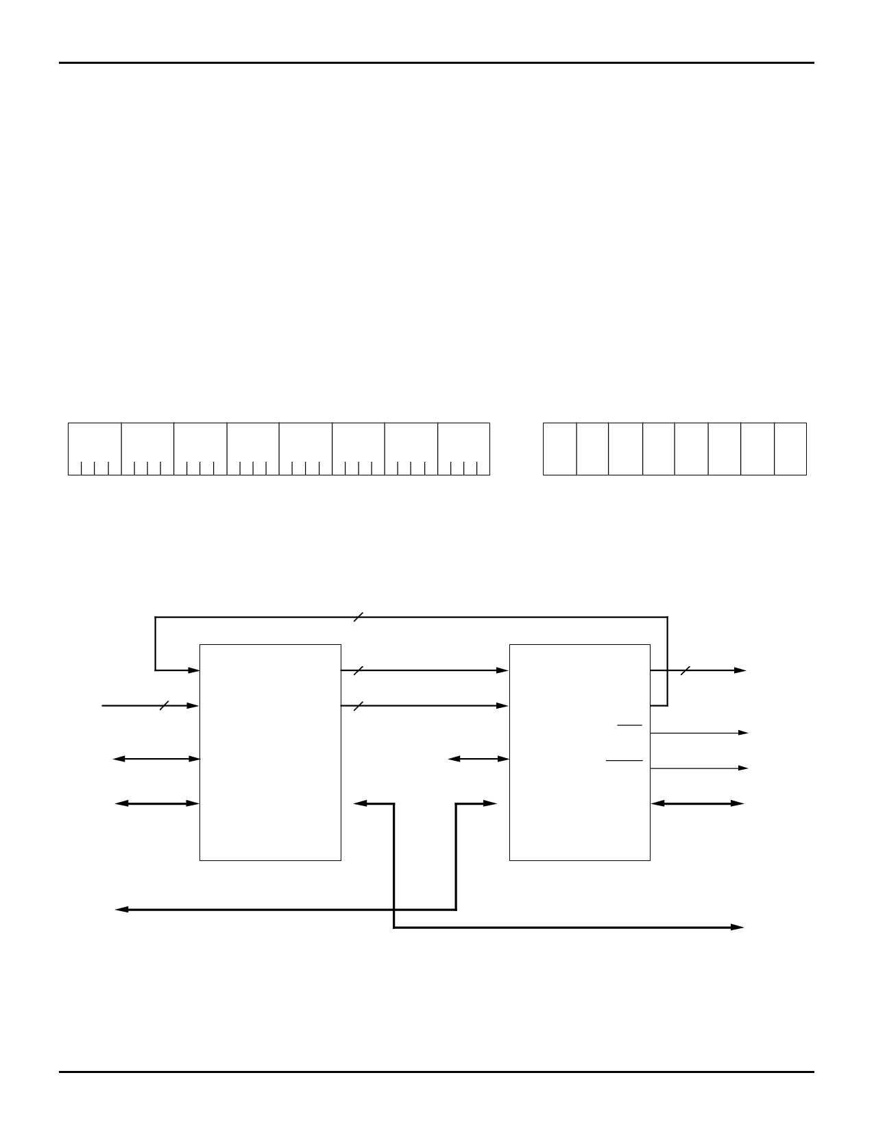
Two IDT49C465 EDC units, connected as shown below,
provide all the logic needed for single-bit error correction, and
double-bit error detection, of a 64-bit data field. The “Slice
Identification” Table gives the CODE ID1,0 values needed for
distinguishing the upper 32 bits from the lower 32 bits. Final
generated checkbits, ERR and MERR (indicates multiple
errors) signals come from the upper slice, the IC with CODE
ID1,0=11. Control signals not shown are connected to both
units in parallel.
Data-In bits 0 through 31 are connected to the same
numbered inputs of the EDC with CODE ID1,0=10, while
Data-In bits 32 through 63 are connected to data inputs 0 to
31, respectively, for the EDC unit with CODE ID1,0=11.
The 72-bit data format of data and checkbits is indicated
below.
Correction of single-bit errors in the 64-bit configuration
requires a simultaneous exchange of partial checkbits and
partial syndrome bits between the upper and lower units.
Syndrome bits are generated by an exclusive-OR of the
generated checkbits with the checkbits read from memory.
For example, Sn is the XOR of checkbits read and checkbits
generated. During data correction, the syndrome bits are
used to complement (correct) single-bit errors in the data bits.
For double or multiple-bit error detection, the data available as
output by the Pipeline Latch is not defined.
Critical AC performance data is provided in the Table “Key
AC Calculations”, which illustrates the delays that are critical
to 64-bit cascaded performance. As indicated, a summation
of propagation delays is required when cascading these units.
64-BIT DATA FORMAT
DATA
BYTE 7 BYTE 6 BYTE 5 BYTE 4 BYTE 3 BYTE 2 BYTE 1 BYTE 0
63 56 55 48 47 40 39 32 31 24 23 16 15 8 7
0
CHECKBITS
C7 C6 C5 C4 C3 C2 C1 C0
2552 drw 17
64-BIT HARDWARE CONFIGURATION
8 PARTIAL–CHECKBITS (CORRECT ONLY)
CHECKBITS–IN
8
SYSTEM DATA 0–31
SYSTEM DATA 32–63
PCBI0–7
CBI0–7
P0–3
CBO0–7
SYO0–7
PCBI0–7
8 PARTIAL–CHECKBITS
(GENERATE ONLY)
CBI0–7
8 PARTIAL–SYNDROME
(DETECT/CORRECT)
P0–3
CBO0–7
SYO0–7
8 FINAL CHECKBITS
(GENERATE ONLY)
ERR
(DETECT AND CORRECT)
MERR
SD0–31
IDT49C465
LOWER EDC
(CODE ID 1,0 = 10)
SD0–31
MD0–31
IDT49C465
UPPER EDC
(CODE ID 1,0 = 11)
MEMORY DATA 32–63
MEMORY DATA 0–31
2552 drw 18
11.7
14
Share Link: 