HWD075DGE-A(2003) Ver la hoja de datos (PDF) - Power-One Inc.
Número de pieza
componentes Descripción
Fabricante
HWD075DGE-A Datasheet PDF : 12 Pages
| |||
HWD DC/DC Series Data Sheet
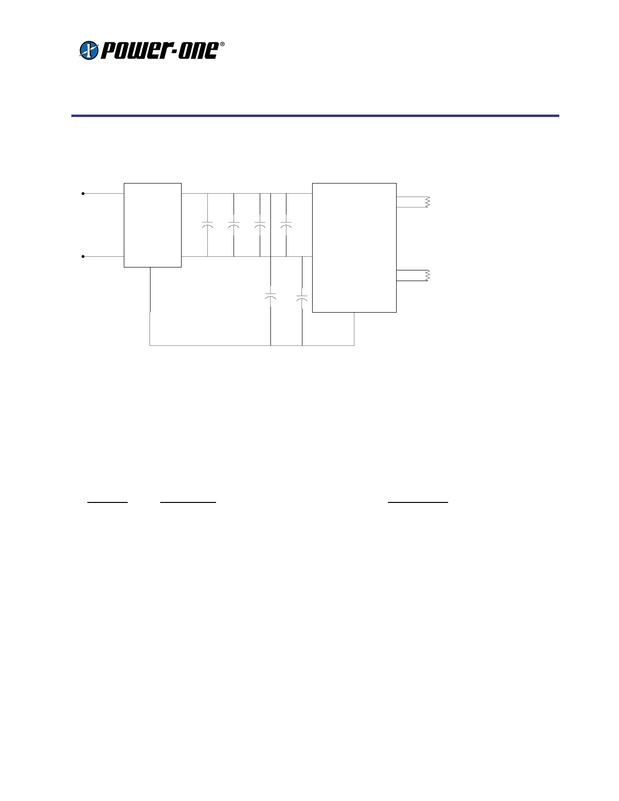
FC100V10
+
HWD15DGE
Vin+
Vo1
-Vo1
LOAD1
VIN
C1
C2
C3
C4
-
GND
Vin-
Vo2
C5
C6
CASE
-Vo2
LOAD2
Figure 3. Input Filter Configuration Required to Meet CISPR 22 Class A for Conducted Emissions
Ref. Des
C1, 2
C3
C4
C5, 6
F1
Table 11.Part List for Input Filter
Description
0.47uF @100V MLC Capacitor (1812)
100uF @ 100V Alum. Electrolytic Capacitor
22uF@ 100V Alum. Electrolytic Capacitor
0.01uF MLC Capacitor
FC100V10 Input Filter Module
Manufacture
AVX or Equivalent (Equiv.)
Nichicon NRSZ Series or Equiv.
United Chemicon KMG Series or Equiv.
AVX or Equiv.
Power-One
FEATURE DESCRIPTIONS
Output Overvoltage Clamp
The output overvoltage clamp consists of a separate control loop, independent of the primary control loop. This
control loop has a higher voltage setpoint than the primary loop. In a fault condition the converter goes into
“Hiccup Mode”, and the output overvoltage clamp ensures that the output voltage does not exceed Vo,clamp,max.
This secondary control loop provides a redundant voltage control that reduces the risk of output overvoltage.
Output Current Protection
To provide protection in an output overload or short circuit condition, the converter is equipped with current limiting
circuitry and can endure the fault condition for an unlimited duration. At the point of current-limit inception, the
converter goes into “Hiccup Mode”, causing the output current to be limited both in peak and duration. The
converter operates normally once the output current is brought back into its specified range.
Enable
Two enable options are available. Positive Logic Enable and Negative Logic Enable. Positive Logic Enable turns
the converter ON during a logic-high voltage on the enable pin, and OFF during a logic-low. Negative Logic Enable
turns the converter OFF during a logic-high and ON during a logic-low.
REV. JUN 27, 2003
Page 7 of 12
Share Link: 