HV9903 Ver la hoja de datos (PDF) - Supertex Inc
Número de pieza
componentes Descripción
Fabricante
HV9903 Datasheet PDF : 12 Pages
| |||
HHVV99990033
lower standard value is 3.3µH (10% tolerance) and
the corrected rating is then:
ICORRECTED
320mA
3.7µH
3.3µH
359mA
Inductor data sheets may rate the inductor in terms of
DC current, RMS current, or saturation current. The
DC or saturation ratings should be used. Confirm that
the inductor is not saturating by observing the SW pin.
When an inductor saturates, current begins to climb
rapidly. This condition is evidenced by a breakpoint in
the SW voltage waveform as indicated in the diagram
below. Normally, the voltage at the SW pin should be
a fairly linear ramp, as the linear rise in inductor
current through the SW resistance produces a linear
voltage ramp. When the inductor saturates, the rapid
rise in current produces a likewise rapid rise in SW
voltage. Test using an HV9903 with a low switching
frequency.
SW Waveform Showing Inductor Saturation
VIN
Gnd
Normal
Saturated
indicated when the SW voltage is at the supply
voltage level (with some ringing).
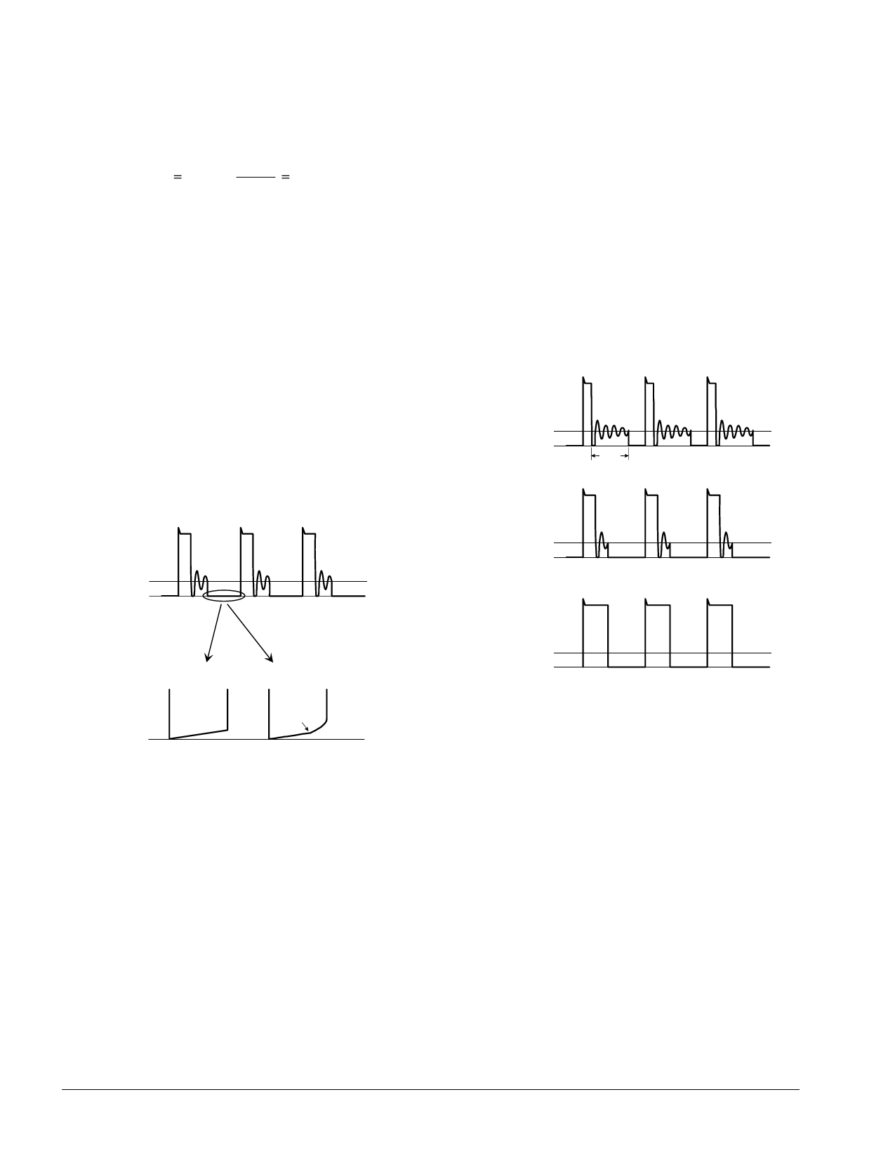
The following graphs show the SW waveform with
various inductor values and can assist in selecting an
inductor. The top graph shows an inductor value that
is acceptable, however, greater efficiency can be
achieved by increasing inductance. The bottom graph
shows continuous mode operation, which must be
avoided.
SW Waveform with Various Inductor Values
Inductance too low
VIN
Gnd
idle
time
Inductance ideal
VIN
Gnd
VIN
Gnd
Inductance too high
(continuous mode)
Gnd
Note: ringing or noise may be present.
Also, confirm that the driver is operating in
discontinuous mode by observing the voltage at the
SW pin while at minimum supply and maximum LED
current. For worst-case test purposes, select
components within their tolerance range as follows:
Inductor: high value
LED: high voltage drop
HV9903: high switching frequency
Some ringing in the SW waveform will be evident, but
is not a concern as the energy is very low. About 10-
15% idle time should be allowed to assure
discontinuous mode operation. Idle time is the
interval when there is no inductor current flowing, as
Capacitor Selection
Proper selection of CDD and COUT is essential to the
efficient operation of the LED driver. Both CDD and
COUT should be around 1µF with good high frequency
characteristics (low ESR and ESL). Ceramic
capacitors are a practical choice for their high
volumetric efficiency and good high frequency
characteristics, but pay attention to the capacitor’s
voltage coefficient. Some small, high value ceramic
capacitors can lose 75% of their capacitance at their
rated voltage! X5R, Y5V, and Z5U formulations are
more susceptible to this effect, as well as possessing
higher temperature coefficients. X7R formulations are
a better choice.
The voltage rating of CDD should be greater than the
maximum supply voltage. To be compatible with the
HV9903’s open LED protection, COUT’s voltage rating
should be 35V or more.
6
Share Link: 