HT46R232 Ver la hoja de datos (PDF) - Holtek Semiconductor
Número de pieza
componentes Descripción
Fabricante
HT46R232 Datasheet PDF : 50 Pages
| |||
HT46R232/HT46C232
Functional Description
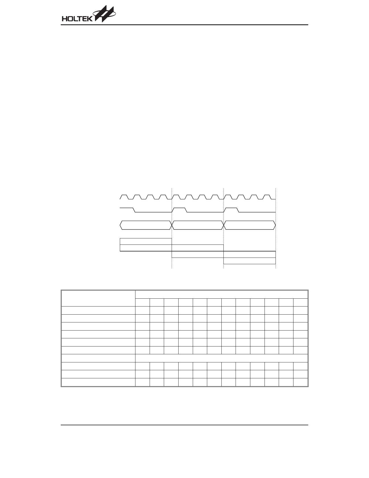
Execution Flow
The system clock is derived from either a crystal or an
RC oscillator. It is internally divided into four
non-overlapping clocks. One instruction cycle consists
of four system clock cycles. Instruction fetching and ex-
ecution are pipelined in such a way that a fetch takes
one instruction cycle while decoding and execution
takes the next instruction cycle. The pipelining scheme
makes it possible for each instruction to be effectively
executed in a cycle. If an instruction changes the value
of the program counter, two cycles are required to com-
plete the instruction.
Program Counter - PC
The program counter (PC) is 12 bits wide and it controls
the sequence in which the instructions stored in the pro-
gram ROM are executed. The contents of the PC can
specify a maximum of 4096 addresses. After accessing
a program memory word to fetch an instruction code,
the value of the PC is incremented by 1. The PC then
points to the memory word containing the next instruc-
tion code. When executing a jump instruction, condi-
tional skip execution, loading a PCL register, a
subroutine call, an initial reset, an internal interrupt, an
external interrupt, or returning from a subroutine, the PC
manipulates the program transfer by loading the ad-
dress corresponding to each instruction.
The conditional skip is activated by instructions. Once
the condition is met, the next instruction, fetched during
the current instruction execution, is discarded and a
dummy cycle replaces it to get a proper instruction; oth-
erwise proceed to the next instruction.
The lower byte of the PC (PCL) is a readable and
writeable register (06H). Moving data into the PCL per-
forms a short jump. The destination is within 256 loca-
tions.
When a control transfer takes place, an additional
dummy cycle is required.
T1 T2 T3 T4 T1 T2 T3 T4 T1 T2 T3 T4
S y s te m C lo c k
O S C 2 ( R C o n ly )
PC
PC
PC +1
PC +2
F e tc h IN S T (P C )
E x e c u te IN S T (P C -1 )
F e tc h IN S T (P C + 1 )
E x e c u te IN S T (P C )
Execution Flow
F e tc h IN S T (P C + 2 )
E x e c u te IN S T (P C + 1 )
Mode
Program Counter
*11 *10 *9 *8 *7 *6 *5 *4 *3 *2 *1 *0
Initial Reset
000000000000
External Interrupt
000000000100
Timer/Event Counter 0 Overflow 0 0 0 0 0 0 0 0 1 0 0 0
Timer/Event Counter 1 Overflow 0 0 0 0 0 0 0 0 1 1 0 0
A/D Converter Interrupt
I2C Bus Interrupt
000000010000
000000010100
Skip
Program Counter + 2
Loading PCL
*11 *10 *9 *8 @7 @6 @5 @4 @3 @2 @1 @0
Jump, Call Branch
#11 #10 #9 #8 #7 #6 #5 #4 #3 #2 #1 #0
Return from Subroutine
S11 S10 S9 S8 S7 S6 S5 S4 S3 S2 S1 S0
Program Counter
Note: *11~*0: Program counter bits
#11~#0: Instruction code bits
S11~S0: Stack register bits
@7~@0: PCL bits
Rev. 1.40
6
November 23, 2005
Share Link: 