HT48RA0-1 Ver la hoja de datos (PDF) - Holtek Semiconductor
Número de pieza
componentes Descripción
Fabricante
HT48RA0-1 Datasheet PDF : 33 Pages
| |||
HT48RA0-1/HT48CA0-1
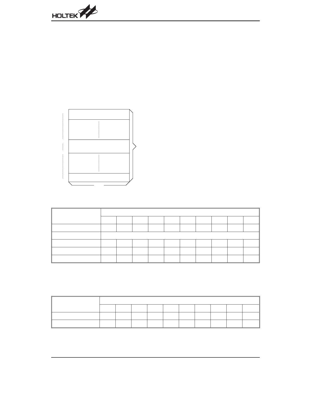
· Table location
Any location in the EPROM space can be used as
look-up tables. The instructions TABRDC [m] (the cur-
rent page, one page=256 words) and TABRDL [m]
(the last page) transfer the contents of the lower-order
byte to the specified data memory, and the
higher-order byte to TBLH (08H). Only the destination
of the lower-order byte in the table is well-defined, the
other bits of the table word are transferred to the lower
portion of TBLH, the remaining 2 bits are read as ²0².
The Table Higher-order byte register (TBLH) is read
only. The table pointer (TBLP) is a read/write register
(07H), where P indicates the table location. Before ac-
cessing the table, the location must be placed in
TBLP. The TBLH is read only and cannot be restored.
000H
D e v ic e in itia liz a tio n p r o g r a m
n00H
L o o k - u p ta b le ( 2 5 6 w o r d s )
nFFH
P ro g ra m
L o o k - u p ta b le ( 2 5 6 w o r d s )
3FFH
1 4 b its
N o te : n ra n g e s fro m 0 to 3
Program Memory
All table related instructions need 2 cycles to complete
the operation. These areas may function as normal
program memory depending upon the requirements.
Stack Register - STACK
This is a special part of the memory used to save the
contents of the program counter (PC) only. The stack is
organized into one level and is neither part of the data
nor part of the program space, and is neither readable
nor writeable. The activated level is indexed by the stack
pointer (SP) and is neither readable nor writeable. At a
subroutine call the contents of the program counter are
pushed onto the stack. At the end of a subroutine sig-
naled by a return instruction (RET), the program counter
is restored to its previous value from the stack. After a
chip reset, the SP will point to the top of the stack.
If the stack is full and a ²CALL² is subsequently exe-
cuted, stack overflow occurs and the first entry will be
lost (only the most recent return address is stored).
Data Memory - RAM
The data memory is designed with 42´8 bits. The data
memory is divided into two functional groups: special
function registers and general purpose data memory
(32´8). Most of them are read/write, but some are read
only.
The special function registers include the indirect ad-
dressing register (00H), the memory pointer register
(MP;01H), the accumulator (ACC;05H) the program
Mode
Program Counter
*9
*8
*7
*6
*5
*4
*3
*2
*1
*0
Initial reset
0
0
0
0
0
0
0
0
0
0
Skip
Program Counter + 2
Loading PCL
*9
*8
@7 @6 @5 @4 @3 @2 @1 @0
Jump, call branch
#9
#8
#7
#6
#5
#4
#3
#2
#1
#0
Return from subroutine
S9
S8
S7
S6
S5
S4
S3
S2
S1
S0
Note: *9~*0: Program counter bits
#9~#0: Instruction code bits
Program Counter
S9~S0: Stack register bits
@7~@0: PCL bits
Instruction(s)
TABRDC [m]
TABRDL [m]
Table Location
*9
*8
*7
*6
*5
*4
*3
*2
*1
*0
P9
P8 @7 @6 @5 @4 @3 @2 @1 @0
1
1
@7 @6 @5 @4 @3 @2 @1 @0
Note: *9~*0: Table location bits
P9~P8: Current program counter bits
Table Location
@7~@0: Table pointer bits
Rev. 1.40
5
December 21, 2005
Share Link: 