HT47C20-1 Ver la hoja de datos (PDF) - Holtek Semiconductor
Número de pieza
componentes Descripción
Fabricante
HT47C20-1 Datasheet PDF : 41 Pages
| |||
Indirect Addressing Register
Location 00H and 02H are indirect addressing registers
that are not physically implemented. Any read/write op-
eration of [00H] and [02H] access data memory pointed
to by MP0 (01H) and MP1 (03H) respectively. Reading
location 00H or 02H indirectly will return the result 00H.
Writing indirectly results in no operation.
The function of data movement between two indirect ad-
dressing registers are not supported. The memory
pointer registers, MP0 and MP1, are both 8-bit registers
which can be used to access the data memory by com-
bining corresponding indirect addressing registers.
Only MP0 can be applied to data memory, while MP1
can be applied to data memory and LCD display mem-
ory.
Accumulator
The accumulator is closely related to ALU operations. It
is also mapped to location 05H of the data memory and
is capable of carrying out immediate data operations.
The data movement between two data memory loca-
tions must pass through the accumulator.
Arithmetic and Logic Unit - ALU
This circuit performs 8-bit arithmetic and logic operation.
The ALU provides the following functions:
· Arithmetic operations (ADD, ADC, SUB, SBC, DAA)
· Logic operations (AND, OR, XOR, CPL)
· Rotation (RL, RR, RLC, RRC)
· Increment and Decrement (INC, DEC)
· Branch decision (SZ, SNZ, SIZ, SDZ ....)
The ALU not only saves the results of a data operation
but can change the status register.
HT47R20A-1/HT47C20-1
Status Register - STATUS
This 8-bit register (0AH) contains the zero flag (Z), carry
flag (C), auxiliary carry flag (AC), overflow flag (OV),
power down flag (PDF) and watchdog time-out flag
(TO). It also records the status information and controls
the operation sequence.
With the exception of the TO and flags, bits in the status
register can be altered by instructions like most other
registers. Any data written into the status register will not
change the TO or PDF flags. In addition it should be
noted that operations related to the status register may
give different results from those intended. The TO and
PDF flags can only be changed by the Watchdog Timer
overflow, system power-up, clearing the Watchdog
Timer and executing the HALT instruction.
The Z, OV, AC and C flags generally reflect the status of
the latest operations.
In addition, on entering the interrupt sequence or exe-
cuting the subroutine call, the status register will not be
pushed onto the stack automatically. If the contents of
the status are important and if the subroutine can cor-
rupt the status register, precautions must be taken to
save it properly.
Interrupts
The HT47R20A-1/HT47C20-1 provides an external in-
terrupt, an internal timer/event counter interrupt, an in-
ternal time base interrupt, and an internal real time clock
interrupt. The interrupt control register 0 (INTC0;0BH)
and interrupt control register 1 (INTC1;1EH) both con-
tain the interrupt control bits to set the enable or disable
and interrupt request flags.
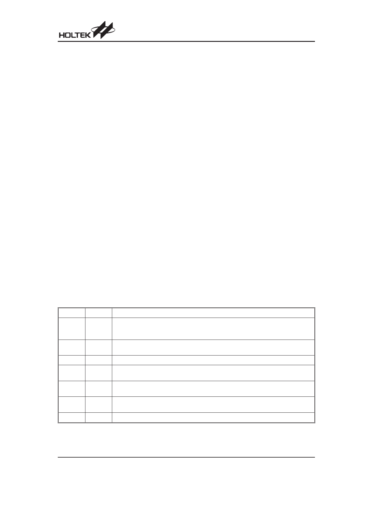
Bit No.
0
1
2
3
4
5
6, 7
Label
C
AC
Z
OV
PDF
TO
¾
Function
C is set if the operation results in a carry during an addition operation or if a borrow does not
take place during a subtraction operation; otherwise C is cleared. C is also affected by a ro-
tate through carry instruction.
AC is set if the operation results in a carry out of the low nibbles in addition or no borrow from
the high nibble into the low nibble in subtraction; otherwise AC is cleared.
Z is set if the result of an arithmetic or logic operation is 0; otherwise Z is cleared.
OV is set if the operation results in a carry into the highest-order bit but not a carry out of the
highest-order bit, or vice versa; otherwise OV is cleared.
PDF is cleared when either a system power-up or executing the CLR WDT instruction. PDF
is set by executing the HALT instruction.
TO is cleared by a system power-up or executing the CLR WDT or HALT instruction. TO is
set by a WDT time-out.
Unused bit, read as ²0²
STATUS (0AH) Register
Rev. 1.80
10
June 23, 2008
Share Link: 