HFA1112A Ver la hoja de datos (PDF) - Intersil
Número de pieza
componentes Descripción
Fabricante
HFA1112A Datasheet PDF : 14 Pages
| |||
HFA1112, HFA1112A
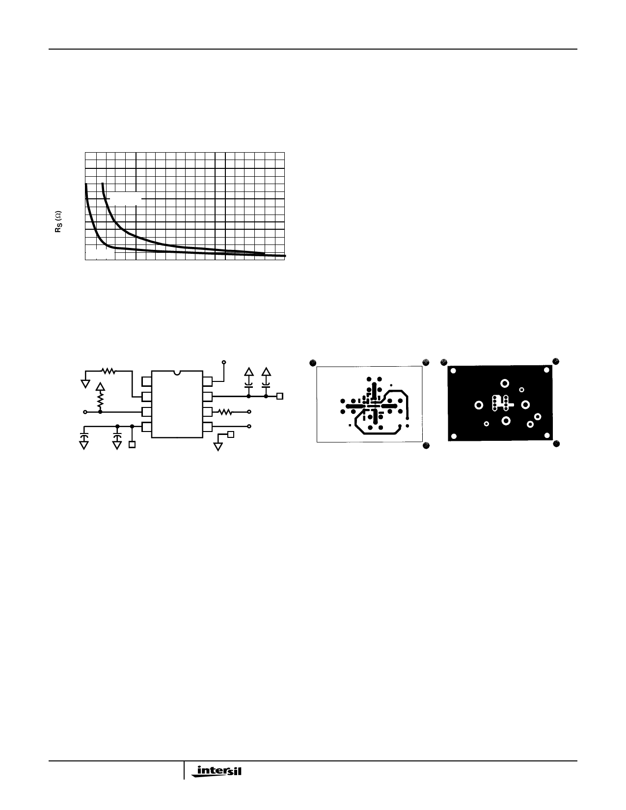
(as illustrated in the curves), the maximum bandwidth is
obtained without sacrificing stability. Even so, bandwidth
does decrease as you move to the right along the curve.
For example, at AV = +1, RS = 50Ω, CL = 30pF, the overall
bandwidth is limited to 300MHz, and bandwidth drops to
100MHz at AV = +1, RS = 5Ω, CL = 340pF.
50
45
40
AV = +1
35
30
25
20
15
10
5
0
AV = +2
0 40 80 120 160 200 240 280 320
LOAD CAPACITANCE (pF)
360 400
FIGURE 1. RECOMMENDED SERIES OUTPUT RESISTOR vs
LOAD CAPACITANCE
Evaluation Board
The performance of the HFA1112 may be evaluated using
the HFA11XX Evaluation Board, slightly modified as follows:
1. Remove the 500Ω feedback resistor (R2), and leave the
connection open.
2. a. For AV = +1 evaluation, remove the 500Ω gain setting
resistor (R1), and leave pin 2 floating.
b. For AV = +2, replace the 500Ω gain setting resistor with
a 0Ω resistor to GND.
The layout and modified schematic of the board are shown
in Figure 2.
To order evaluation boards (part number HFA11XXEVAL),
please contact your local sales office.
∞ (AV = +1)
or 0Ω (AV = +2)
R1
1
50Ω
2
IN
3
4
10µF 0.1µF
-5V
VH
8 0.1µF
7
50Ω
6
10µF
+5V
OUT
5
GND
VL
GND
TOP LAYOUT
VH
1
+IN
VLOVU- T V+
GND
FIGURE 2. EVALUATION BOARD SCHEMATIC AND LAYOUT
BOTTOM LAYOUT
5
Share Link: 