HDMP-1687 Ver la hoja de datos (PDF) - HP => Agilent Technologies
Número de pieza
componentes Descripción
Fabricante
HDMP-1687
HP => Agilent Technologies

HDMP-1687 Datasheet PDF : 16 Pages
| |||
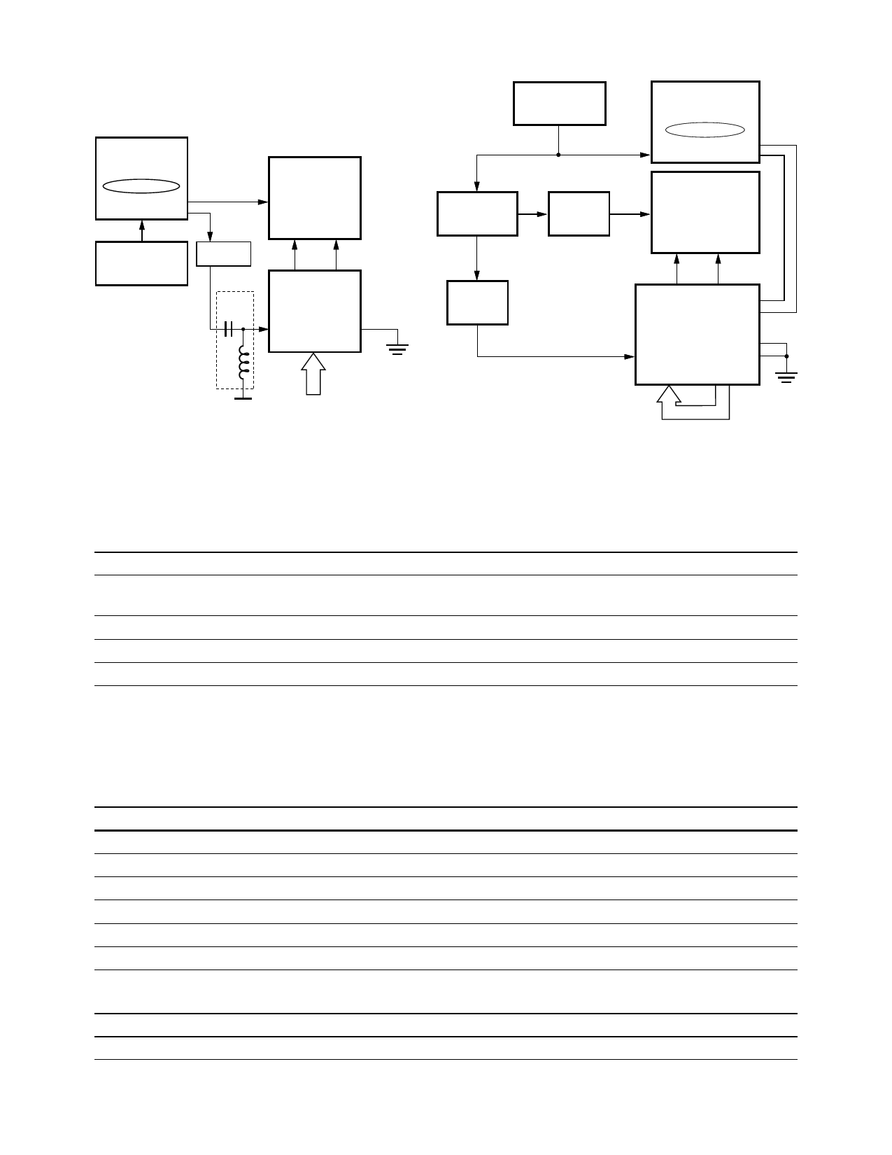
A 70841B
PATTERN
GENERATOR*
0000011111
+ DATA
– DATA
1.25 GHz
A 70311A
CLOCK SOURCE
125 MHz
VARIABLE
DELAY
BIAS
TEE
A 83480A
OSCILLOSCOPE
TRIGGER
CH1 CH2
+SOi –SOi
HDMP-1687
RFCT
LOOP
TXi(0-9)
*PATTERN
GENERATOR
PROVIDES A
DIVIDE BY 10
FUNCTION
1.4 V
0011111000
(STATIC K28.7)
A. BLOCK DIAGRAM OF RJ MEASUREMENT METHOD
A 70311A
CLOCK SOURCE
1.25 GHz
DIVIDE BY 10
CIRCUIT
(DUAL OUTPUT)
DIVIDE
BY 2
A 70841B
PATTERN
GENERATOR
+K28.5, –K28.5
+ DATA
– DATA
A 83480A
OSCILLOSCOPE
TRIGGER
CH1 CH2
VARIABLE
DELAY
TTL
125 MHz
+SOi –SOi
–SIi
+SIi
HDMP-1687
RFCT
SYNC
LOOP
TXi(0..9) RXi(0..9)
B. BLOCK DIAGRAM OF DJ MEASUREMENT METHOD
Figure 8. Transmitter jitter measurement method.
Thermal and Power Characteristics (TRx)
T = 0°C Ambient to 85°C Case, VCC = 3.15 V to 3.45 V
Symbol
Parameter
Units
Typ.
Max.
PD, TRx
Transceiver Power Dissipation, Outputs Connected
W
per Recommended Bias Terminations with Idle Pattern
2.6
3.3
θJA[1]
θJC[2]
ψJT[3]
Thermal Resistance: Junction to Ambient
°C/W
15.8
Thermal Resistance: Junction to Case
°C/W
2.5
Thermal Characterization Parameter: Junction to Package Top °C/W
1.1
Notes:
1. θJA is measured in a still air environment at 25°C on a standard 3 x 3" FR4 PCB as specified in EIA/JESD 51-7.
2. θJC data relevant for packages used with external heat sink.
3. To determine the actual junction temperature in a given application, use the following: TJ = TT + (ψJT x PD), where TT is the case temperature
measured on the top center of the package and PD is the power being dissipated.
I/O Type Definitions
I/O Type
Definition
I-TTL
Input TTL, floats high when left open
O-TTL
Output TTL
HS_OUT
50 Ω matched output driver. Will drive AC coupled 50 Ω loads. PECL Level Compatible (Figure 10).
HS_IN
PECL Level Compatible. Must be AC coupled (Figure 10).
C
External Circuit Node
S
Power Supply or Ground
Pin Input Capacitance (TRx)
Symbol
Parameter
CINPUT
Input Capacitance on TTL Input Pins
Units
pF
Typ.
Max.
1.6
9
Share Link: