GS-R1005 Ver la hoja de datos (PDF) - STMicroelectronics
Número de pieza
componentes Descripción
Fabricante
GS-R1005 Datasheet PDF : 7 Pages
| |||
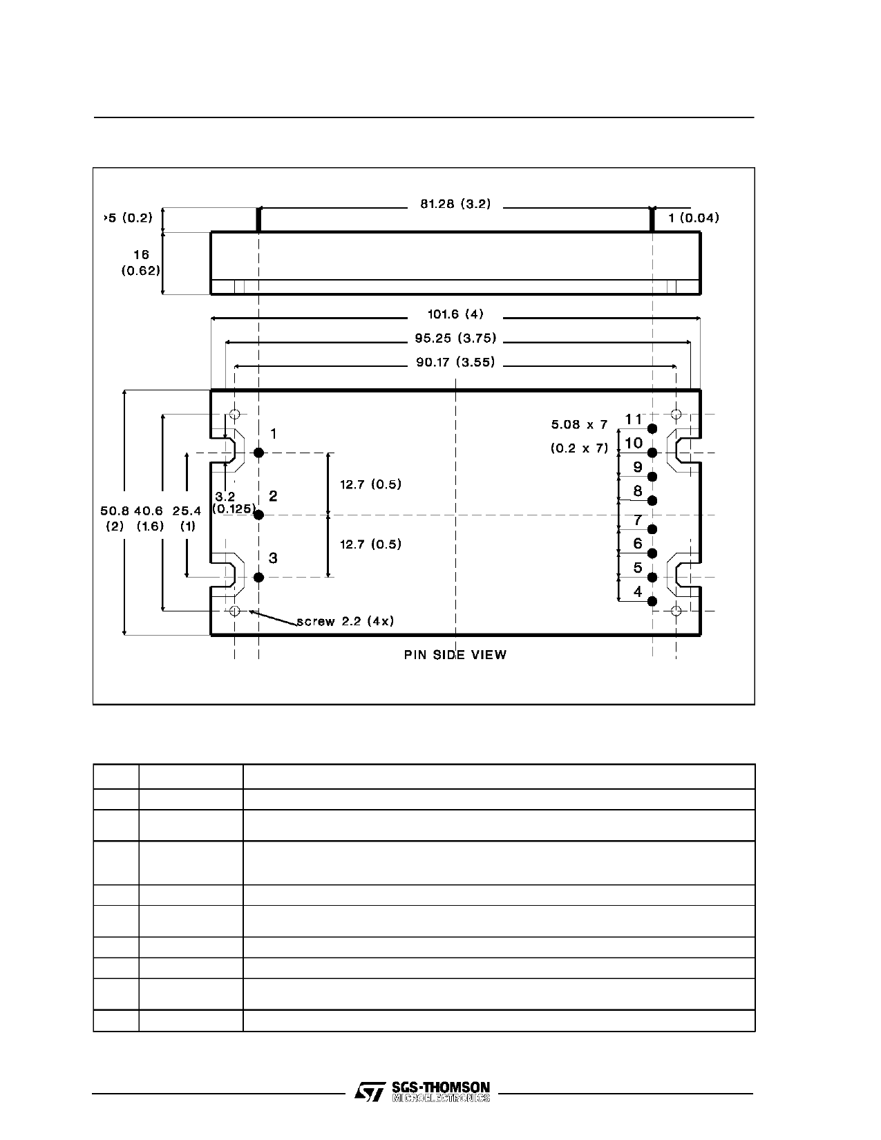
CONNECTION DIAGRAM AND MECHANICAL DATA
GS-R1005
Package R. Dimensions in mm (inches).
PIN DESCRIPTION
Pin
Function
1
GND Input
2
Inhibit
3
+ Vin
4,5
6
7
8
9
10,11
+ Vout
+ Sense
Sync
Parallel
- Sense
GND Output
Description
Return for input voltage source. Internally connected to pin 10,11.
The converter is ON (Enable) when this pin is unconnected or the voltage applied is lower
than 1.2V. The converter is OFF (Inhibit) for a control voltage in the range of 2 to 24V.
DC Input voltage; recommended maximum voltage is 36V.
External capacitor between pin 3 and pin 1 is mandatory; recommended value is
470µF/50V for switching application.
+5V output voltage.
Senses the remote load high side. To be connected to pin 4,5 when remote sense is not
used.
Synchronization output. See figures 1,2,3,4. Open when not used.
Parallel output. See figures 1,2,3,4. Open when not used.
Senses the remote load return. To be connected to pin 10,11 when remote sense is not
used. In parallel configuration, take care to connect all -S pins together (see figures 1,2,3,4).
Return for output current path. Internally connected to pin 1.
3/7
Share Link: 