GM19371 Ver la hoja de datos (PDF) - Gamma Microelectronics Inc.
Número de pieza
componentes Descripción
Fabricante
GM19371 Datasheet PDF : 10 Pages
| |||
GM19371
BOOST WHITE LED DRIVER
WITH OVP
LED Current Control
The LED current is controlled by the feedback resistor (R1, in Fig 1). The feedback reference is 95mV. The
LED current is 95mV/R1. The formula and table 1 for R1 selection are shown below. R1=95mV/ILED
Table 1 RSET resistor value selection
ILED
R1 (Ω)
5
19.1
10
9.53
15
6.34
20
4.75
60
1.56
350
0.22
Dimming Control
1. Using a PWM Signal to CTRL Pin
With the PWM signal applied to the CTRL pin, the GM19371 is turned on or off by the PWM signal.
The LED operate at either zero or full current. The average LED current increases proportionally with
the duty cycle of the PWM signal. A 0% duty cycle will turn off the GM19371 and corresponds to zero
LED current. A 100% duty cycle corresponds to full current. The typical frequency range of the PWM
signal is 100Hz to 1KHz. The magnitude of the PWM signal should be higher than the minimum CTRL
voltage high.
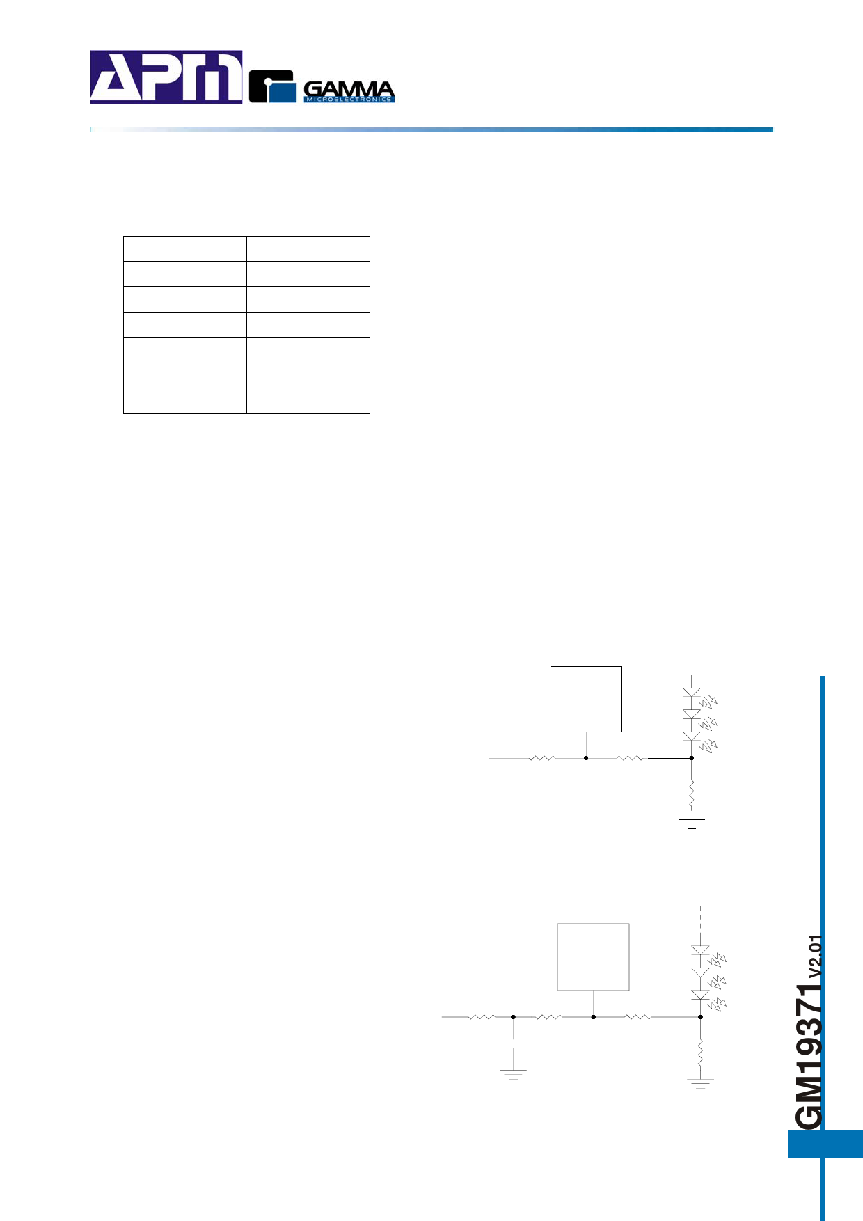
2. Using a DC Voltage
For some applications, the preferred method of
brightness control is a variable DC voltage to adjust
the LED current. The dimming control using a DC
voltage is shown in below figure 6. As the DC
GM19371
voltage increases, the voltage drop on R1 increases
and the voltage drop on RSET decreases. Thus, the
LED current decreases. The selection of R1 and R2 VDC
R2
should make the current from the variable DC
90K
source much smaller than the LED current and
R1
5K
RSET
6.3Ω
much larger than the FB pin bias current. For VDC
range from 0V to 2V, the selection of resistors in
Figure 6
below figure gives dimming control of LED current
from 0mA to 15mA.
3. Using a DC Voltage
For The filtered PWM signal can be considered as
an adjustable DC voltage. It can be used to replace
the variable DC voltage source in dimming control.
The circuit is show in figure 7
GM19371
PWM
100K
R2
R1
90K
5K
0.1μF
Figure 7
RSET
6.3Ω
7
Share Link: 