GA100TS60SF Ver la hoja de datos (PDF) - International Rectifier
Número de pieza
componentes Descripción
Fabricante
GA100TS60SF Datasheet PDF : 7 Pages
| |||
GA100TS60SF
Bulletin I27201 rev. A 01/06
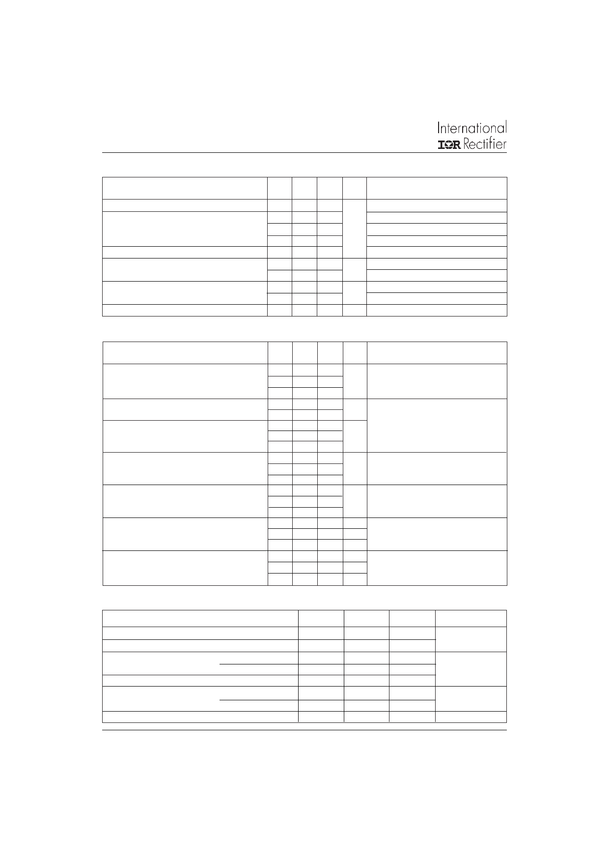
Electrical Characteristics @ TJ = 25°C (unless otherwise specified)
Parameters
Min Typ Max Units Test Conditions
VBRCES Collector-to-Emitter Breakdown Voltage 600
V VGE = 0V, IC = 1mA
VCE(on) Collector-to-Emitter Voltage
1.11 1.28
VGE = 15V, IC = 100A
1.39
IC = 200A
1.08 1.22
VGE = 15V, IC = 100A, TJ = 125°C
VGE(th) Gate Threshold Voltage
3
6
IC = 0.25mA
ICES
Collector-to-Emiter Leakage
1 mA VGE = 0V, VCE = 600V
Current
10
VGE = 0V, VCE = 600V, TJ = 125°C
VFM
Diode Forward Voltage drop
1.44 1.96 V IC = 100A, VGE = 0V
1.25 1.54
IC = 100A, VGE = 0V, TJ = 125°C
IGES
Gate-to-Emitter Leakage Current
± 250 nA VGE = ± 20V
Switching Characteristics @ TJ = 25°C (unless otherwise specified)
Parameters
Min Typ Max Units Test Conditions
Qg
Qge
Qgc
tr
tf
Eon
Eoff
Ets
Eon
Eoff
Ets
Cies
Coes
Cres
trr
Irr
Qrr
trr
Irr
Qrr
Total Gate Charge
Gate-Emitter Charge
Gate-Collector Charge
Rise Time
Fall Time
Turn-On Switching Energy
Turn-Off Switching Energy
Total Switching Energy
Turn-On Switching Energy
Turn-Off Switching Energy
Total Switching Energy
Input Capacitance
Output Capacitance
Reverse Transfer Capacitance
Diode Reverse Recovery Time
Diode Peak Reverse Current
Diode Recovery Charge
Diode Reverse Recovery Time
Diode Peak Reverse Current
Diode Recovery Charge
640 700
108 120
230 300
0.45
1.0
4
6
23 29
27 35
6 12
35 40
41 52
16250
1040
190
91 155
10.6 15
500 900
180 344
17 20.5
1633 2315
nC IC = 100A
VCC = 400V
VGE = 15V
µs IC = 100A, VCC = 480V, VGE = 15V
Rg = 15Ω
mJ
mJ IC = 100A, VCC = 480V, VGE = 15V
Rg = 15Ω, TJ = 125°C
pF VGE = 0V
VCC = 30V
f = 1.0 MHz
ns IF = 50A, dIF/dt = 200A/µs
A VRR = 200V
nC
ns IF = 50A, dIF/dt = 200A/µs
A VRR = 200V
nC TJ = 125°C
Thermal- Mechanical Specifications
Parameters
Min
Typ
Max
TJ
Operating Junction Temperature Range
- 40
150
TSTG
Storage Temperature Range
- 40
125
RthJC
Junction-to-Case per Switch
0.16
Per Diode
0.48
RthCS
Case-to-Sink
Per Module
0.1
T
Mounting torque Case to heatsink
4
Case to terminal 1, 2, 3
3
Weight
185
Units
°C
°C/ W
Nm
g
2
www.irf.com
Share Link: 