FSL127H Ver la hoja de datos (PDF) - Fairchild Semiconductor
Número de pieza
componentes Descripción
Fabricante
FSL127H Datasheet PDF : 15 Pages
| |||
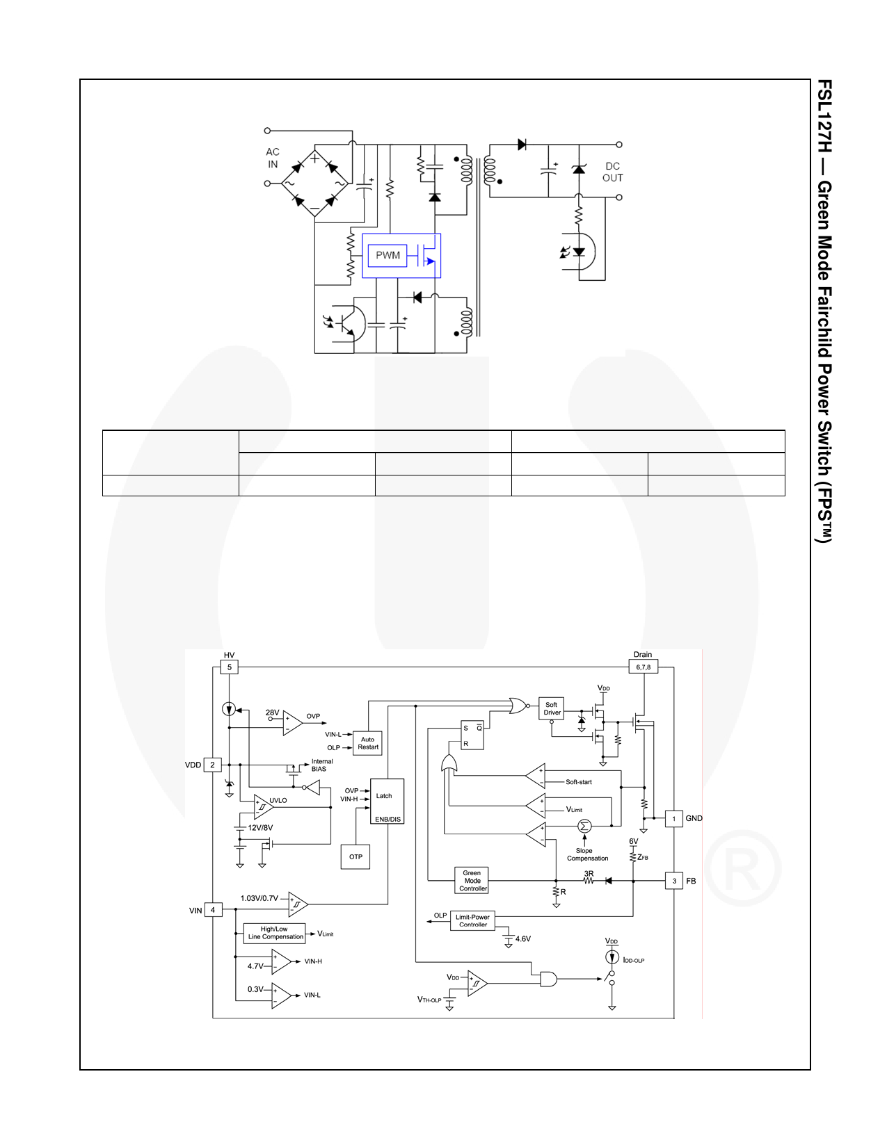
Application Diagram
HV
Drain
VIN
FB
VDD GND
Figure 1. Typical Flyback Application
Output Power Table(1)
Product
230VAC ± 15%(2)
Adapter(3)
Open Frame(4)
85-265VAC
Adapter(3)
Open Frame(4)
FSL127H
14W
20W
11W
16W
Notes:
1. The maximum output power can be limited by junction temperature.
2. 230 VAC or 100/115 VAC with doublers.
3. Typical continuous power in a non-ventilated enclosed adapter with sufficient drain pattern as a heat sink,
at TA=50°C ambient.
4. Maximum practical continuous power in an open-frame design with sufficient drain pattern as a heat sink,
at TA=50°C ambient.
Internal Block Diagram
© 2010 Fairchild Semiconductor Corporation
FSL127H • Rev. 1.0.2
Figure 2. Internal Block Diagram
2
www.fairchildsemi.com
Share Link: 