FAN7554 Ver la hoja de datos (PDF) - Fairchild Semiconductor
Número de pieza
componentes Descripción
Fabricante
FAN7554 Datasheet PDF : 22 Pages
| |||
FAN7554
Operation Description
The FAN7554 has all the basic features of the current mode SMPS control IC. Its basic configuration includes the UVLO with
6V hysteresis, a band gap reference, the oscillator that can oscillate up to 500kHz according to Rt/Ct (connected externally), a
PWM logic circuit , a gate driver, and the feedback circuit that has the current source and soft start function. The FAN7554 has
various functions such as an over load protection, an over current protection, and an over voltage protection. The over load
protection forces the FAN7554 to stop its operation if the load current is higher than the preset value. The protection circuit
can also be prevented from operating during transient states by ensuring that a certain amount of the time passes before the
protection circuit operates. The shutdown circuit is configured for an auto-restart, so the FAN7554 automatically restarts when
Vcc drops to 9V (stop voltage).
Start-Up
The start-up circuit is made up of an under voltage lock out (UVLO), the protection for low voltage conditions, and the 5V
reference (Vref), which supplies bias voltage to the control circuit after start-up. The start voltage of the UVLO is 15V , and
the stop voltage after turn on is 9V. It has a 6V hysteresis. The minimum operating current for start-up threshold is typically
100uA, and this can reduce the power dissipation on the start-up resistor. The Vref is composed of the band gap reference
circuit with its superior temperature characteristics and supplies power to all the FAN7554 circuits and Rt/Ct, with the
exceptions of the ULVO circuit and ON/OFF control circuit.
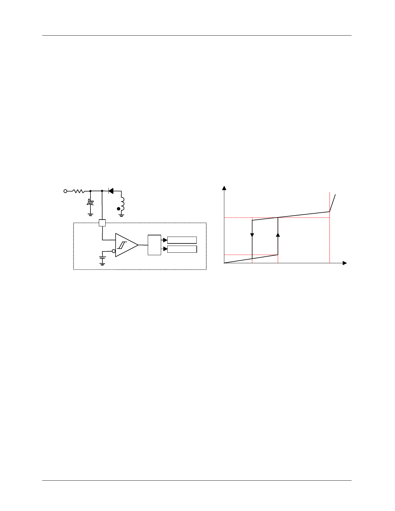
DC Link
Icc(mA)
VCC
7
UVLO
15V/9V
7.0
5V
Internal bias
Vref Good logic
0.01
FAN7554
Figure 11. Low Current Start-Up & Bandgap Reference Circuit
Vcc (V)
9
15
Figure 12. Start-Up & Circuit Characteristics
Soft Start
The SMPS output load usually contains a capacitive load component. During initial start-up, the output voltage increases at a
fixed time constant because of this component. If the feedback loop, which controls the output voltage, was to start without
the soft start circuit, the feedback loop would appear to be open during initial start-up , so, at start-up, the feedback voltage
applied to the PWM comparator’s inverting input (-) reaches its maximum value(1V).
During this time, the peak value of the drain current would stay at the maximum value, and the maximum power would be
delivered to the secondary load side from the start. When the maximum power is delivered to the secondary side for this initial
fixed time, the entire circuit is seriously stressed. The use of a soft start can avoid such stresses. At start-up, the soft start
capacitor Cs is charged by 1mA and 100uA current sources.
The voltage of the inverting terminal of the PWM comparator increases to 1/3 of the Cs voltage at a fixed time constant.
Subsequently, the drain peak current is limited by the gradual increase in the Cs voltage and this causes the output voltage to
increase smoothly. When the Cs voltage becomes greater than 3V, the diode Ds turns off consequently, the feedback capacitor
Cfb is charged by 1mA and 5uA current sources. This charge voltage determines the comparator’s inverting voltage. Then, Cs
voltage charges to 5V by 100uA current source. The soft start capacitor Cs is discharged when the UVLO good logic starts, so
the soft start is repeated at re-start.
8
Share Link: 