EM78R808A Ver la hoja de datos (PDF) - ELAN Microelectronics
Número de pieza
componentes Descripción
Fabricante
EM78R808A Datasheet PDF : 63 Pages
| |||
EM78808
8-bit Micro-controller
R1 (TCC)
TCC data buffer. Increased by 16.38KHz or by the instruction cycle clock (controlled by CONT register).
Written and read by the program as any other register.
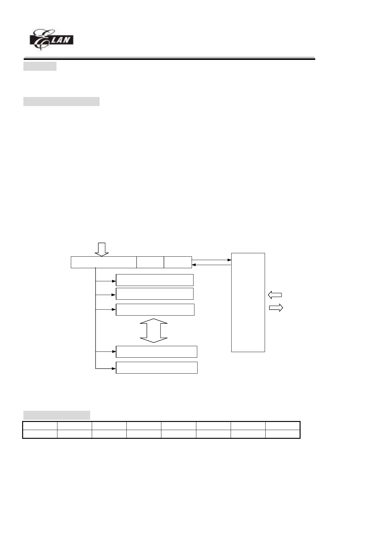
R2 (Program Counter)
The structure is depicted in Fig. 5.
Generates 32K × 13 on-chip PROGRAM ROM addresses to the relative programming instruction codes.
"JMP" instruction allows the direct loading of the low 10 program counter bits.
"CALL" instruction loads the low 10 bits of the PC, PC+1, and then push into the stack.
"RET'' ("RETL k", "RETI") instruction loads the program counter with the contents at the top of stack.
"MOV R2,A" allows the loading of an address from the A register to the PC, and the ninth and tenth bits are
cleared to "0''.
"ADD R2,A" allows a relative address be added to the current PC, and contents of the ninth and tenth bits are
cleared to "0''.
"TBL" allows a relative address be added to the current PC, and contents of the ninth and tenth bits don't change.
The most significant bit (A10~A14) will be loaded with the content of bit PS0~PS3 in the status register (R5)
upon the execution of a "JMP'', "CALL'', "ADD R2,A'', or "MOV R2,A'' instruction.
If a interrupt trigger, PROGRAM ROM will jump to address8 at page0. The CPU will store ACC,R3 status and
R5 PAGE automatically, it will restore after instruction RETI.
R5(PAGE)
CALL and
INTERRUPT
PC A14 A13 A12 A11 A10
A9 A8 A7~A0
00000 PAGE0 0000~03FF
00001 PAGE1 0400~07FF
00010 PAGE2 0800~0BFF
RET
RETL
RETI
11110 PAGE30 7800~7BFF
STACK1
STACK2
STACK3
STACK4
STACK5
STACK6
STACK7
STACK8
STACK9
:
:
STACK30
STACK31
STACK32
store
ACC,R3,R5(PAGE)
restore
11111 PAGE31 7C00~7FFF
Fig.5 Program counter organization
R3 (Status Register)
7
6
5
4
3
2
1
0
PAGE IOCP1S IOCPAGE
T
P
Z
DC
C
Bit 0 (C) : Carry flag
Bit 1 (DC) : Auxiliary carry flag
Bit 2 (Z) : Zero flag
Bit 3 (P) : Power down bit.
Set to 1 during power on or by a "WDTC" command and reset to 0 by a "SLEP" command.
Bit 4 (T) : Time-out bit.
Set to 1 by the "SLEP" and "WDTC" command, or during power up and reset to 0 by WDT timeout.
______________________________________________________________________________________________________________________________________________________
* This specification is subject to change without notice.
8/1/2004 (V3.1)
13
Share Link: 