ELM415 Ver la hoja de datos (PDF) - Elm Electronics
Número de pieza
componentes Descripción
Fabricante
ELM415 Datasheet PDF : 5 Pages
| |||
ELM415
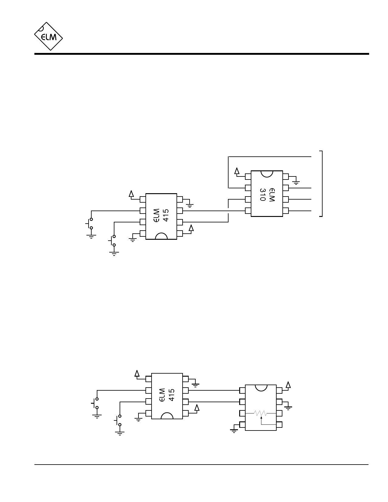
Example Applications
Figure 1 shows the ELM415 used to interface two
pushbutton switches to an ELM310 stepper motor
controller, so that the motor position can be manually
controlled. For simplicity, the stepper motor and its
drive transistors are not shown in the diagram. Notice
that pin 5 has been tied to VDD in order to enable the
automatic repeat function, allowing the motor to move
‘continuously’ if a button is held down. Also, because
there are internal pullup resistors, the two pushbuttons
have been connected directly to the inputs without
further support circuitry.
Using the ELM310 to control a stepper motor has
many advantages – low cost, low power, and ease of
use, for example. The disadvantage, however, is that
the integrated circuit is capable of responding very
quickly to input signals. This could result in multiple
steps of the motor, and perceived erratic motor
operation, if the input were not ‘debounced’ by a circuit
such as the ELM415.
A
+5V
1
8
To winding
+5V
2
7
B drive circuits
5
4
3
6
C
Clockwise
6
3
7
2
+5V
8
1
4
5
D
Counter
clockwise
Figure 1. Controlling a stepper motor
The circuit of Figure 2 is very similar to the one
above, but it uses an Analog Devices AD5220 Digital
Potentiometer as the controlled device. The up and
down buttons are used to ‘move’ the wiper between
the two ends (pins 3 and 6). As shown, when stepped
in the Up direction, the AD5220 moves the wiper
towards the pin 3 end of the pot, while Down moves it
towards pin 6.
The AD5220 expects to have a Count signal that
is normally low, pulsing to a high level in order to
change the resistance, so pin 4 is connected to a low
(VSS) level, as shown. Some devices, such as the
Maxim MAX5160, require an inverted Count output,
which can be provided by simply tying pin 4 to VDD
instead of VSS.
Up
Down
VDD
5
6
7
8
4
3
2
VDD
1
VDD
1
8
2 AD5220 7
3
6
4
5
Figure 2. Controlling a digital potentiometer
ELM415DSA
Elm Electronics – Circuits for the Hobbyist
< http://www.elmelectronics.com/ >
4 of 5
Share Link: 