ELM407 Ver la hoja de datos (PDF) - Elm Electronics
Número de pieza
componentes Descripción
Fabricante
ELM407 Datasheet PDF : 10 Pages
| |||
ELM407
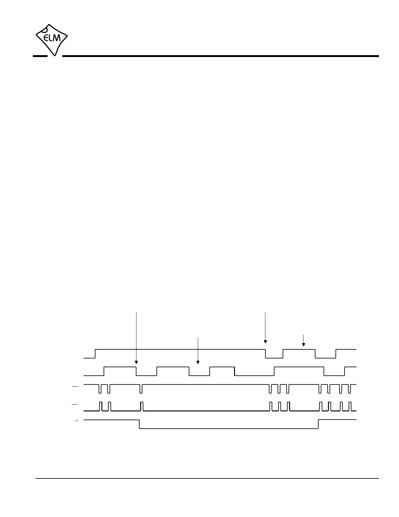
Output Waveforms (continued)
200 µsec. This will result in a write of the wiper
position to non-volatile memory for many ICs (for
example, the ON Semiconductor CAT5112, or the
Intersil X9C102).
Outputs are usually generated each time that one
of the inputs change, so for each full cycle of both of
the inputs, there will be 4 output pulses. This is what is
known as 4x decoding. The other type of decoder that
is very common is the 2x decoder, as used by the
ELM406. We do not currently offer a product with 1x
decoding - if you require one, you will need to use the
ELM401 and decode the signal with your own logic.
Output pulses do not always occur when one of
the inputs change. After startup, the first output can
not be generated until the ELM407 has seen both of
the inputs change, and no output is generated until
then. Also, if an input is seen to be ‘chattering’ the
ELM407 will block the output. Chattering can occur
when the shaft is wiggled, or when it is subjected to
severe vibration. Figure 7 below shows how the
ELM407 handles the multiple inputs due to chatter. If
this logic were not in place, multiple outputs could
occur due to vibration (as found in an automobile, or
an industrial setting), and the setting could ‘creep’ with
time – even though the shaft was not turned.
Generally, output pulses will occur in groups of
four (between each detent), so resistance values or
settings will repeat consistently as the shaft is rotated
in one direction and then in the other. Depending on
when the shaft changes direction, however, the pulses
may not be generated in groups of four. If you are
designing a circuit and require that the controlled
variable must repeat exactly as the shaft is turned in
either direction, you may prefer to use a 2x decoder
such as the ELM406.
Change in B (expecting a change in A)
causes the ELM407 to anticipate a change
in direction, and generate a Down output
A changes, meaning that
the shaft is now rotating,
and pulses can be output
Multiple pulses are ignored while
the ELM407 waits for a change at
the A input
The shaft direction
changes again
A Input
B Input
CS
Clk
U/D
Figure 7. Input Chattering
ELM407DSA
Elm Electronics – Circuits for the Hobbyist
www.elmelectronics.com
8 of 10
Share Link: 