ELM407 Ver la hoja de datos (PDF) - Elm Electronics
Número de pieza
componentes Descripción
Fabricante
ELM407 Datasheet PDF : 10 Pages
| |||
ELM407
Output Waveforms
Once the ELM407 has some bounce-free signals
to work with, it can generate outputs based on them.
The logic to decode the motion of an encoder
shaft is not as simple as it would first appear. Some
authorities recommend simply monitoring an input and
when it changes, provide an output based on the level
of the other input. This does not always work, as the
encoder can output multiple signals from only the ‘A’ or
or only the ‘B’ contact if the shaft is moved ever so
slightly when at the detent or at the mid-point position
(between detents). Simply seeing one input change is
not sufficient to say that there is any significant shaft
rotation.
The ELM407 monitors both ‘A’ and ‘B’ transitions,
and determines the outputs based on the sequence in
which the transitions have occurred. This is a better
way to guarantee that the output signals are generated
properly. The internal logic also performs some self-
checking, and monitors for problems such as an output
pulse being initiated before the previous one had
completed, which might occur for some very fast
inputs (the second one will be ignored in this case).
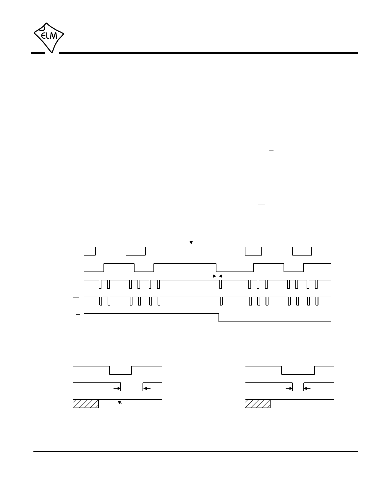
The output of the ELM407 is a series of pulses, as
shown in Figure 4 (a representative pulse has been
enlarged and is shown in Figure 5). When the encoder
is moving in a clockwise direction, the pulses will be
generated with the U/D output at a high level, while a
counter-clockwise rotation of the shaft results in pulses
generated with the U/D output at a low level. The
direction assumes that the encoder is a standard one,
where the ‘A’ signal leads the ‘B’ for a clockwise
rotation.
Figure 6 shows how the output sequence changes
when the Write Enable input (pin 4) is at a high level.
In this case, the Clk output returns high after only
200 µsec, and the CS output remains low for an extra
A Input
B Input
CS
Clk
U/D
direction changes
debounce
delay
Figure 4. Output signals (pin 4 = 0V)
CS
Clk
400 µsec
U/D
this will be low for a
counter-clockwise motion
Figure 5. Up or Clockwise Output
CS
Clk
200 µsec
U/D
Figure 6. Up Output, with Write Enabled
ELM407DSA
Elm Electronics – Circuits for the Hobbyist
www.elmelectronics.com
7 of 10
Share Link: 