7457CLZ Ver la hoja de datos (PDF) - Intersil
Número de pieza
componentes Descripción
Fabricante
7457CLZ Datasheet PDF : 12 Pages
| |||
EL7457
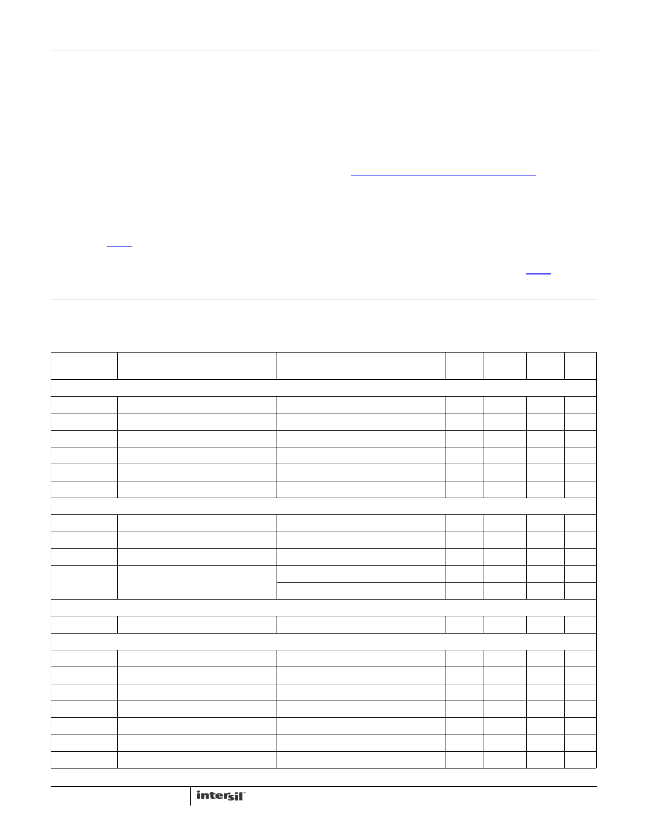
Absolute Maximum Ratings (TA = 25°C)
Supply Voltage (VS+ to VS-) . . . . . . . . . . . . . . . . . . . . . . . . . . .+18V
Input Voltage . . . . . . . . . . . . . . . . . . . . . . . . . . VS- -0.3V, VS+ +0.3V
Continuous Output Current . . . . . . . . . . . . . . . . . . . . . . . . . . 100mA
Storage Temperature Range . . . . . . . . . . . . . . . . . .-65°C to +150°C
Thermal Information
Thermal Resistance
θJA (°C/W) θJC (°C/W)
16 Ld QFN (Notes 4, 5) . . . . . . . . . . . .
43
5
16 Ld SOIC (Notes 6, 7). . . . . . . . . . . .
73
45
16 Ld QSOP (Note 6). . . . . . . . . . . . . .
112
N/A
Ambient Operating Temperature . . . . . . . . . . . . . . . .-40°C to +85°C
Maximum Die Temperature . . . . . . . . . . . . . . . . . . . . . . . . . . +125°C
Power Dissipation . . . . . . . . . . . . . . . . . . . . . . . . . . . . . See Curves
Pb-Free Reflow Profile. . . . . . . . . . . . . . . . . . . . . . . . .see link below
http://www.intersil.com/pbfree/Pb-FreeReflow.asp
CAUTION: Do not operate at or near the maximum ratings listed for extended periods of time. Exposure to such conditions may adversely impact product reliability and
result in failures not covered by warranty.
NOTES:
4. θJA is measured in free air with the component mounted on a high effective thermal conductivity test board with “direct attach” features. See
Tech Brief TB379.
5. For θJC, the “case temp” location is the center of the exposed metal pad on the package underside.
6. θJA is measured with the component mounted on a high effective thermal conductivity test board in free air. See Tech Brief TB379 for details.
7. For θJC, the “case temp” location is taken at the package top center.
IMPORTANT NOTE: All parameters having Min/Max specifications are guaranteed. Typical values are for information purposes only. Unless otherwise noted, all tests
are at the specified temperature and are pulsed tests, therefore: TJ = TC = TA
Electrical Specifications VS+ = +5V, VS- = -5V, VH = +5V, VL = -5V, TA = 25°C, unless otherwise specified.
PARAMETER
DESCRIPTION
CONDITION
MIN
(Note 8) TYP
INPUT
VIH
IIH
VIL
IIL
CIN
RIN
OUTPUT
Logic “1” Input Voltage
Logic “1” Input Current
Logic “0” Input Voltage
Logic “0” Input Current
Input Capacitance
Input Resistance
VIH = 5V
VIL = 0V
2.0
0.1
0.1
3.5
50
ROH
ON Resistance VH to OUTx
IOUT = -100mA
4.5
ROL
ON Resistance VL to OUTx
IOUT = +100mA
4
ILEAK
Output Leakage Current
VH = VS+, VL = VS-
0.1
IPK
Peak Output Current
Source
2.0
Sink
2.0
POWER SUPPLY
IS
Power Supply Current
Inputs = VS+
0.5
SWITCHING CHARACTERISTICS
tR
tF
tRFΔ
tD+
tD-
tDD
tENABLE
Rise Time
Fall Time
tR, tF Mismatch
Turn-Off Delay Time
Turn-On Delay Time
tD-1 - tD-2 Mismatch
Enable Delay Time
CL = 1000pF
CL = 1000pF
CL = 1000pF
CL = 1000pF
CL = 1000pF
CL = 1000pF
13.5
13
0.5
12.5
14.5
2
12
MAX
(Note 8) UNIT
V
10
µA
0.8
V
10
µA
pF
MΩ
6
Ω
6
Ω
10
µA
A
A
1.5
mA
ns
ns
ns
ns
ns
ns
ns
3
FN7288.4
January 26, 2012
Share Link: 