S13B-EH Ver la hoja de datos (PDF) - Unspecified
Número de pieza
componentes Descripción
Fabricante
S13B-EH Datasheet PDF : 6 Pages
| |||
EH CONNECTOR
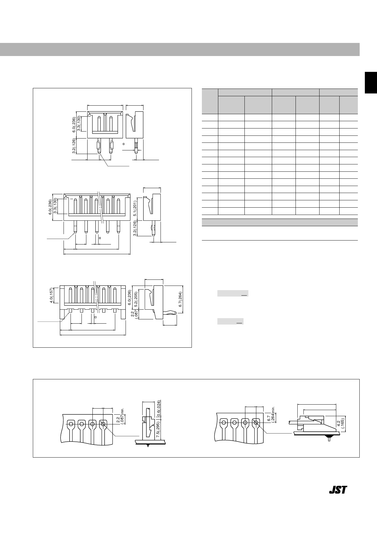
Shrouded header –––––––––––––––––––––––––––––––––––––––––––––––––––––––––
The shrouded headers are interchangeable with those of the HR crimp style and insulation displacement connectors.
Top entry type
(2 circuits)
B
3.8(.150)
Cir-
cuits
Model No.
Top entry Side entry
type
type
Dimensions mm.(in)
Q'ty / box
A
B
Top entry Side entry
type
type
2.5(.098)
(3 to 15 circuits)
0.64
(.025)
A
Circuit No.1
1.6(.063)
3.8(.150)
2 B 2B-EH-A S 2B-EH 2.5( .098) 7.5( .295) 1,000
3 B 3B-EH-A S 3B-EH 5.0( .197) 10.0( .394) 1,000
4 B 4B-EH-A S 4B-EH 7.5( .295) 12.5( .492) 1,000
5 B 5B-EH-A S 5B-EH 10.0( .394) 15.0( .591) 1,000
6 B 6B-EH-A S 6B-EH 12.5( .492) 17.5( .689) 1,000
7 B 7B-EH-A S 7B-EH 15.0( .591) 20.0( .787) 1,000
8 B 8B-EH-A S 8B-EH 17.5( .689) 22.5( .886)
500
9 B 9B-EH-A S 9B-EH 20.0( .787) 25.0( .984)
500
10 B10B-EH-A S10B-EH 22.5( .866) 27.5(1.083) 500
11 B11B-EH-A S11B-EH 25.0( .984) 30.0(1.181) 500
12 B12B-EH-A S12B-EH 27.5(1.083) 32.5(1.280)
500
13 B13B-EH-A S13B-EH 30.0(1.181) 35.0(1.378)
250
14 B14B-EH-A S14B-EH 32.5(1.280) 37.5(1.476)
250
15 B15B-EH-A S15B-EH 35.0(1.378) 40.0(1.575)
250
1,000
1,000
1,000
1,000
500
500
500
500
500
250
250
250
250
250
Circuit No.1
2.5
2.5 (.098)
(.098)
0.64
(.025)
A
B
Side entry type
Circuit No.1
2.5
(.098)
2.5
(.098)
0.64
(.025)
A
B
1.6(.063)
4.2(.165)
3.2
(.126)
Material and Finish
Post: Brass, copper-undercoated, tin/lead plated
Wafer: Nylon 66, UL94V-0, natural (white)
Note:
1. Also available and identified as model BxxB-EH is a top entry type having a
post extension length of 4.0mm(.157")
2. Top entry type headers are not TU¨ V approved.
<For reference> As the color identification,
the following alphabet shall be put in the underlined part.
For availability, delivery and minimum order quantity, contact JST.
<Top entry type>
ex. B2B-EH-A-o o-
(blank)…natural (white)
K…black R…red E…blue Y…yellow M…green
<Side entry type>
ex. S2B-EH-o o-
(blank)…natural (white)
K…black R…red TR…tomato red E…blue Y…yellow
L…lemon yellow M…green O…orange N…brown P…purple
PK…pink H…gray LE…light blue FY…vivid yellow
PC board layout (viewed from soldering side) and Assembly layout –––––––––––––––––––
Top entry type
2.5±0.05 2.5
(.098±.002) (.098)min.
3.8
(.150)
Side entry type
2.5±0.05 1.9
(.098±.002) (.074)min.
10.3(.406)
8.2(.323)
0.9
+
0.1
0
(.035 +.0004)dia.
0.9
+
0.1
0
(.035 +.0004)dia.
Note:
1. Tolerances are non-cumulative: ±0.05mm(±.002" ) for all centers.
2. Hole dimension differ according to the kind of PC board and piercing method. If PC boards made of hard material such as FR-4 are used, the hole dimensions
should be larger. The dimensions above should serve as a guideline. Contact JST for details.
53
Share Link: 