TA2022 Ver la hoja de datos (PDF) - Tripath Technology Inc.
Número de pieza
componentes Descripción
Fabricante
TA2022
Tripath Technology Inc.

TA2022 Datasheet PDF : 31 Pages
| |||
Tripath Technology, Inc. - Technical Information
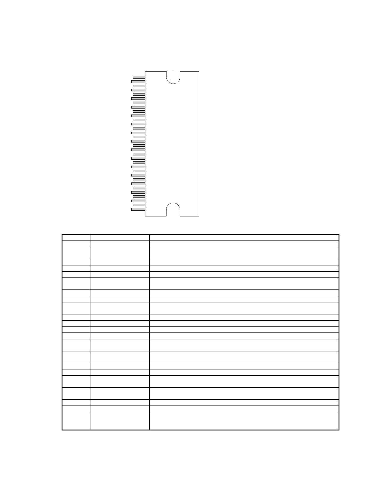
TA2022 PINOUT
32-pin SSIP Package
(Front View)
VBOOT2
1
VN10
2
VN10GND
3
VPP2
4
VN10SW
5
NC
6
OUT2
7
VNN2
8
VNN1
9
OUT1
10
NC
11
VPP1
12
VBOOT1
13
VN10FDBK
14
AGND
15
V5
16
REF
17
VNNSENSE
18
VPPSENSE
19
AGND
20
V5
21
OAOUT1
22
INV1
23
MUTE
24
OAOUT2
25
INV2
26
BIASCAP
27
FBKGND2
28
FBKOUT2
29
FBKGND1
30
FBKOUT1
31
HMUTE
32
PIN DESCRIPTION
Pin
1, 13
2
Function
VBOOT2, VBOOT1
VN10
3
4, 12
5
6
VN10GND
VPP2, VPP1
VN10SW
NC
7,10
OUT2, OUT1
8, 9
VNN2, VNN1
11
NC
14
15, 20
16, 21
17
18
VN10FDBK
AGND
V5
REF
VNNSENSE
19
VPPSENSE
22, 25
23, 26
24
OAOUT1, OAOUT2
INV1, INV2
MUTE
27
BIASCAP
28, 29
30,31
32
FBKGND2, FBKOUT2
FBKGND1, FBKOUT1
HMUTE
Description
Bootstrap voltages for gate drive of high side MOSFET’s
“Floating” supply input. Normally connected to the output of onboard VN10 buck
converter. This voltage must be stable and referenced to VNN.
Power ground for onboard VN10 generator. Electrically tied to the TA2022 case.
Positive power supply input pins.
Switching output voltage for onboard VN10 generator (buck converter).
Not connected internally. May be connected to pin 7 without any loss of
functionality or performance.
Power amplifier outputs.
Negative power supply inputs.
Not connected internally. May be connected to pin 10 without any loss of
functionality or performance.
Feedback for onboard VN10 generator (nominally 11V above VNN)
Analog Ground.
5V power supply input.
Used to set internal bias currents. The pin voltage is typically 1.1V.
Negative supply voltage sense input. This pin is used for both over and under
voltage sensing for the VNN supply.
Positive supply voltage sense input. This pin is used for both over and under
voltage sensing for the VPP supply.
Outputs of Input Stage op amps.
Inverting inputs of Input Stage op amps.
Logic input. A logic high puts the amplifier in mute mode. Ground pin if not used.
Please refer to the section, Mute Control, in the Application Information.
Bandgap reference times two (typically 2.5VDC). Used to set the common mode
voltage for the input op amps. This pin is not capable of driving external circuitry.
Output voltage differential feedback for channel 2.
Output voltage differential feedback for channel 1.
Logic Output. A logic high indicates both amplifiers are muted, due to the mute
pin state, or a “fault” such as an overcurrent, undervoltage, or overvoltage
condition.
6
TA2022 – KLI/1.2/07-04
Share Link: